SECTION 5
electrical wiring diagrams
1. STARTING & CHARGING SYSTEM
1) battery, ignition switch, starter motor, generator & pnp switch circuit
a. CONNECTOR INFORMATION
connector no
(pin no, color) | connecting wiring harness | connector position |
| C101 (4 Pin, Black) | Engine - TCM | Behind Coolant Reservoir |
| C202 (11 Pin, White) | TCM - IP | Behind I/P Fuse Block |
| C204 (4 Pin, White) | Front – IP | Under I/P Fuse Block |
| C205 (18 Pin, Gray) | IP – Engine | Behind I/P Fuse Block |
| G101 | Battery | Under ECM |
| G103 | Engin | Next to #4 Injector |
| G105 | Battery | Next to Starter Motor |
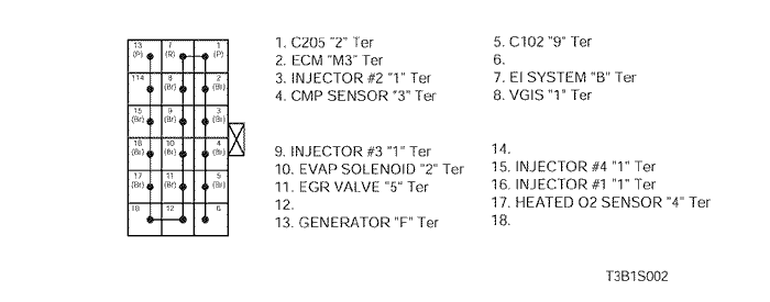
b. CONNECTOR IDENTIFICATION SYMBOL & PIN NUMBER POSITION
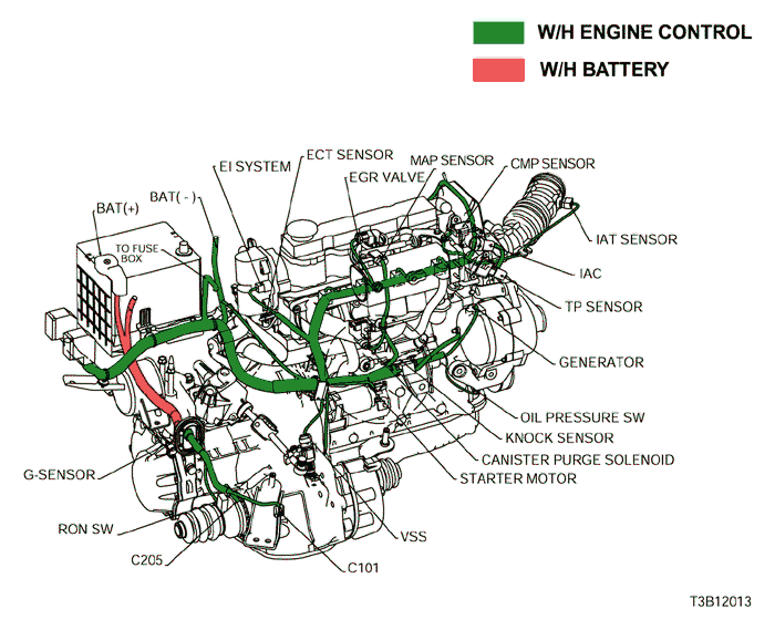
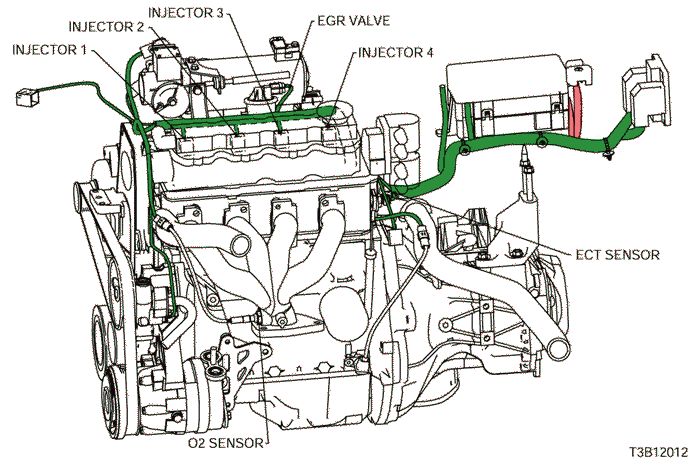
c. POSITION OF CONNECTORS AND GROUNDS
d. SPLICE PACK
s201 (mr-140/hv-240)
sm