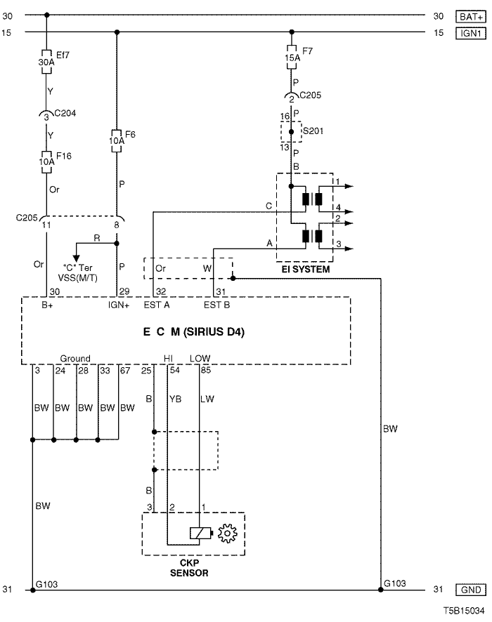
4. ECM (ENGINE CONTROL MODULE) : SIRIUS D4
1) battery power supply, ground, ei system & ckp sensor circuit
a. CONNECTOR INFORMATION
connector no
(pin no, color) | connecting wiring harness | connector position |
| C204 (4 Pin, White) | Front – IP | Under I/P Fuse Block |
| C205 (18 Pin, Gray) | IP – Engine | Behind I/P Fuse Block |
| G103 | Engine | Next to #4 Injector |
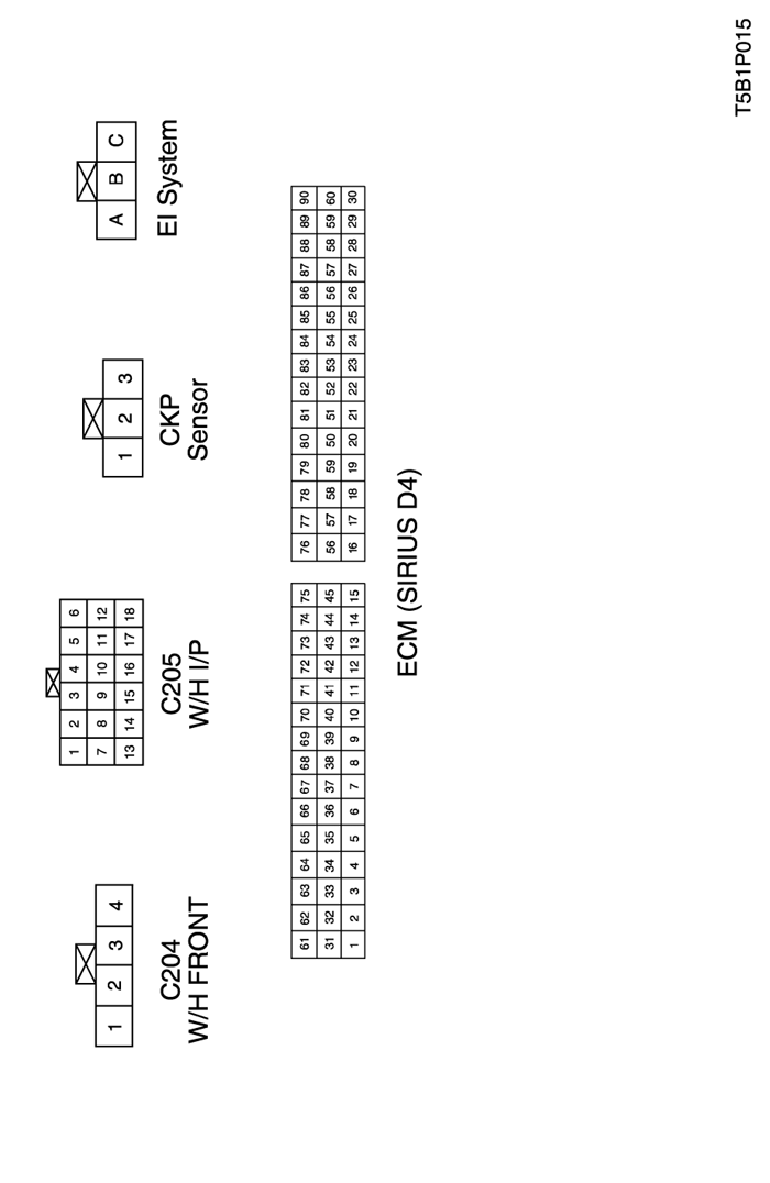
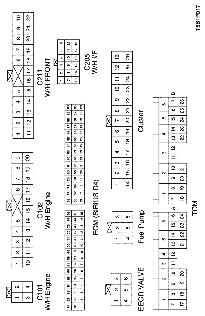
b. CONNECTOR IDENTIFICATION SYMBOL & PIN NUMBER POSITION
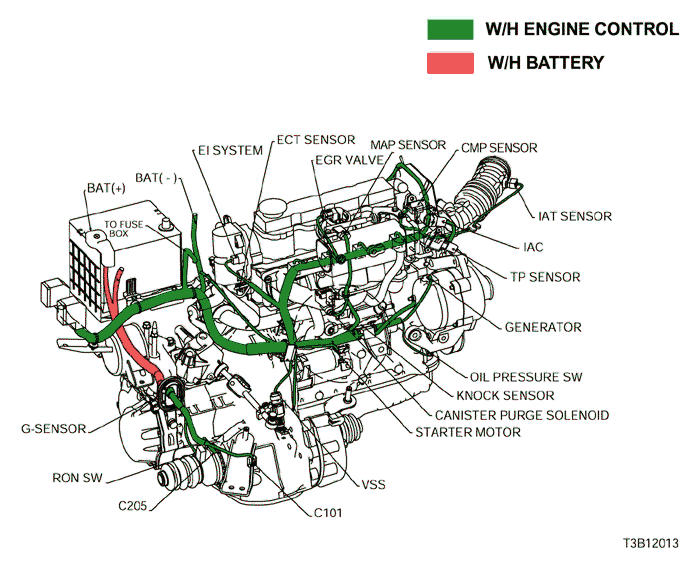
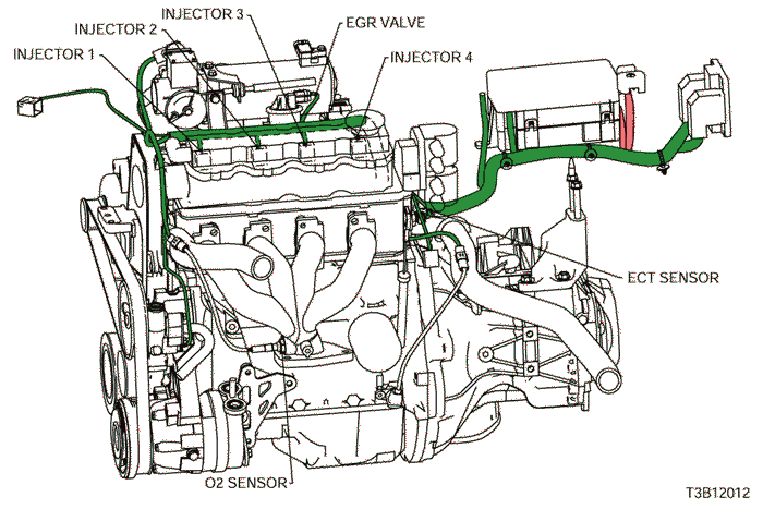
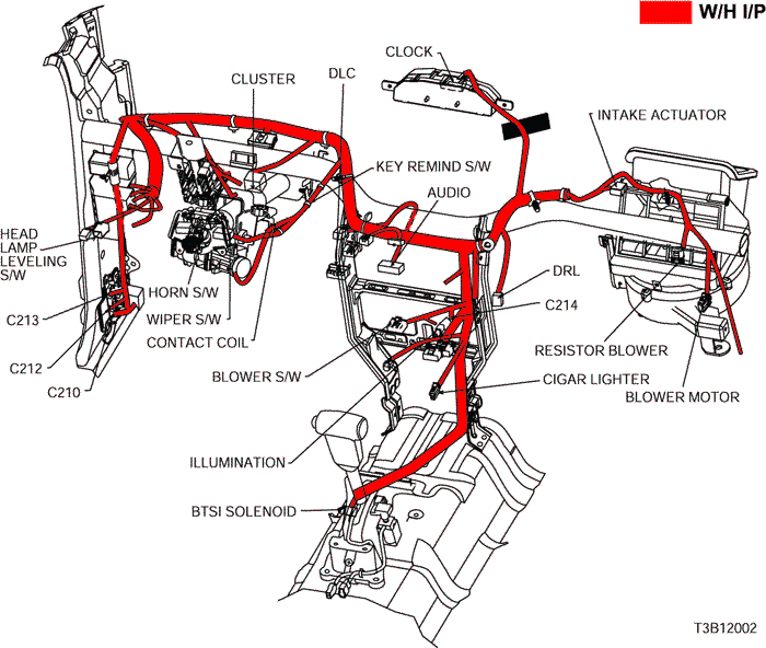
c. POSITION OF CONNECTORS AND GROUNDS
d. SPLICE PACK
s201
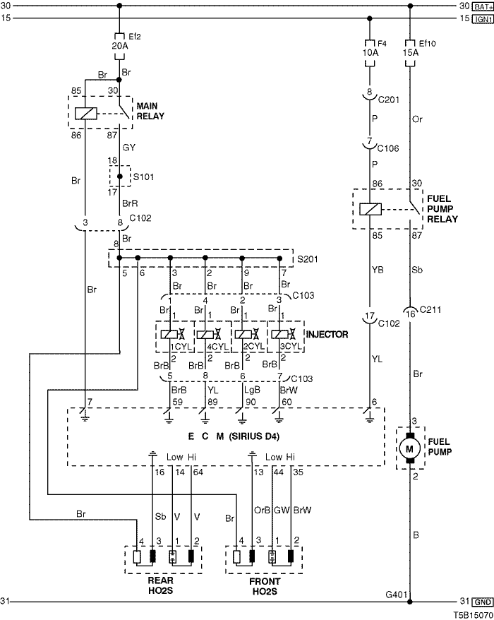
2) fuel pump, injector & o2 sensor circuit
a. CONNECTOR INFORMATION
connector no
(pin no, color) | connecting wiring harness | connector position |
| C102 (20 Pin, White) | Engine – Front | Engine Room Fuse Block |
| C103 (8 Pin, Black) | Engine – Injector | Upper Cylinder |
| C211 (22 Pin, Yellow) | Front – Body | Under Left A Pillar |
| G401 | Body (H/B) | Left Tail Gate Panel |
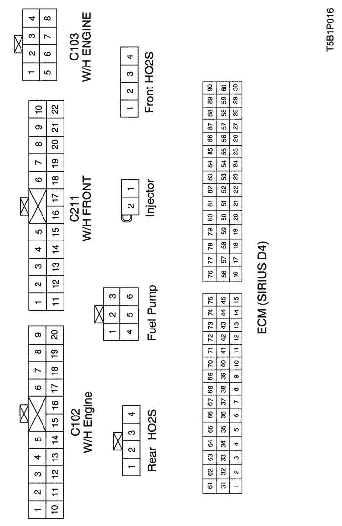
b. CONNECTOR IDENTIFICATION SYMBOL & PIN NUMBER POSITION
c. POSITION OF CONNECTORS AND GROUNDS
d. SPLICE PACK
s101
s201
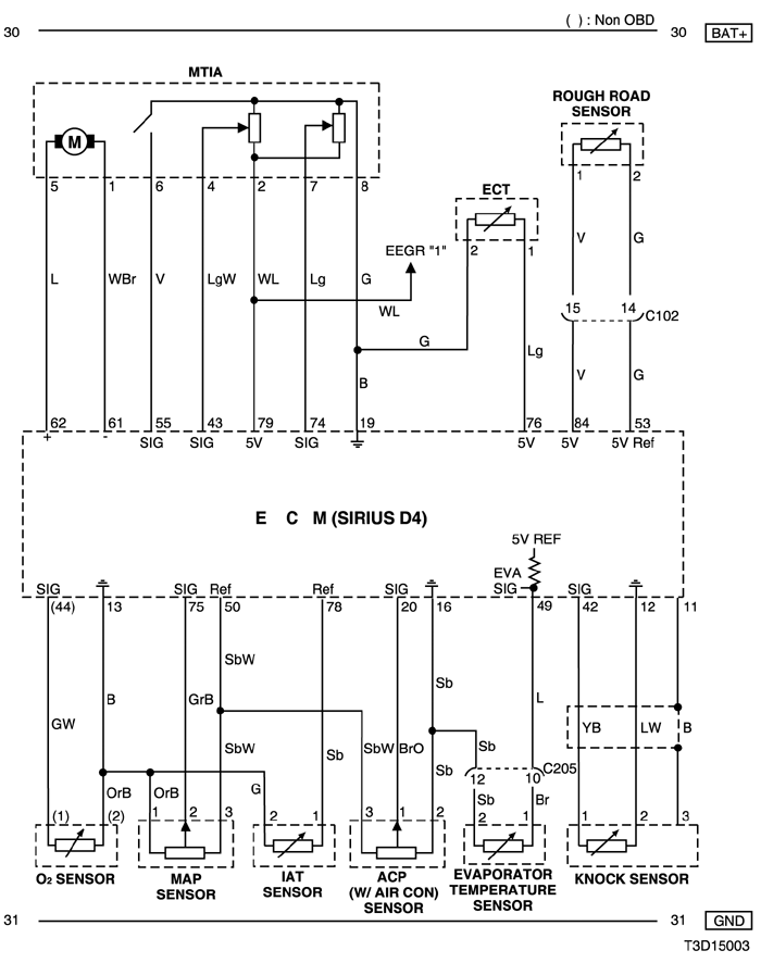
3) mtia & sensor (ect, rough road, o2, map, iat, acp, evaporator temperature & knock) circuit
a. CONNECTOR INFORMATION
connector no
(pin no, color) | connecting wiring harness | connector position |
| C102 (20 Pin, White) | Engine – Front | Engine Room Fuse Block |
| C205 (18 Pin, Gray) | IP – Engine | Behind I/P Fuse Block |
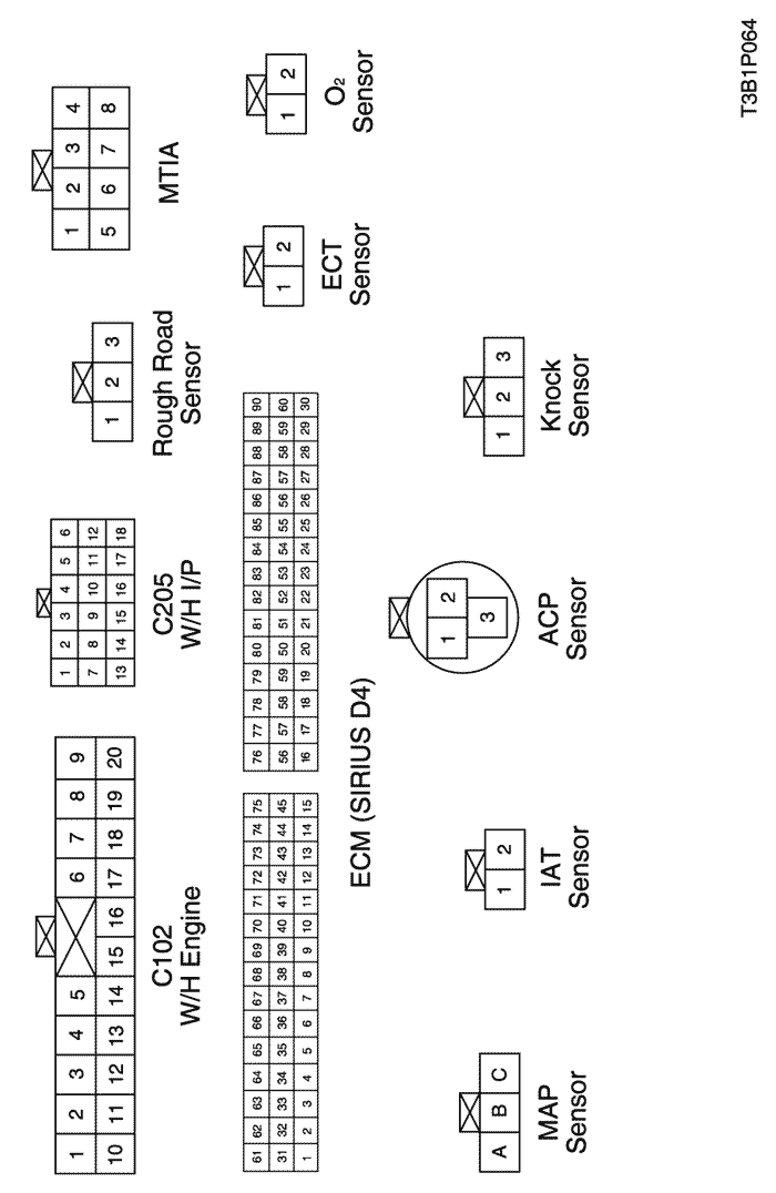
b. CONNECTOR IDENTIFICATION SYMBOL & PIN NUMBER POSITION
c. POSITION OF CONNECTORS AND GROUNDS
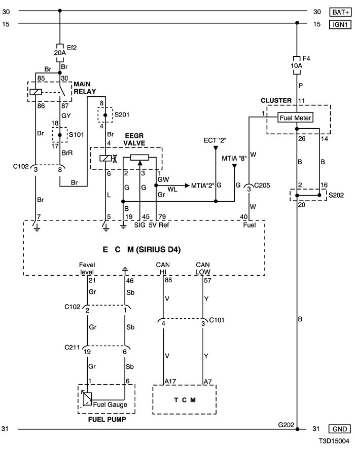
4) cluster, eegr valve, fuel pump & tcm circuit
a. CONNECTOR INFORMATION
connector no
(pin no, color) | connecting wiring harness | connector position |
| C101 (4 Pin, Black) | Engine – TCM | Behind Coolant Reservoir |
| C102 (20 Pin, White) | Engine – Front | Engine Room Fuse Block |
| C205 (18 Pin, Gray) | IP – Engine | Behind I/P Fuse Block |
| C211 (22 Pin, Yellow) | Front – Body | Under Left A Pillar |
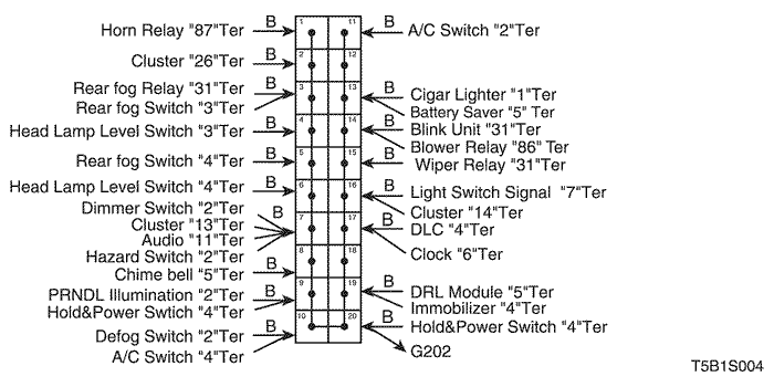
| G202 | IP | Behind Right Ashtray |
b. CONNECTOR IDENTIFICATION SYMBOL & PIN NUMBER POSITION
c. POSITION OF CONNECTORS AND GROUNDS
d. SPLICE PACK
s101
s202
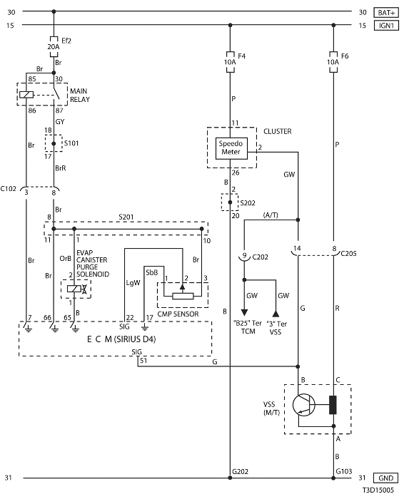
5) cmp sensor, evap canister purge solenoid, cluster & vss circuit
a. CONNECTOR INFORMATION
connector no
(pin no, color) | connecting wiring harness | connector position |
| C102 (20 Pin, White) | Engine – Front | Engine Room Fuse Block |
| C202 (11 Pin, White) | TCM-IP | Behind I/P Fuse Block |
| C205 (18 Pin, Gray) | IP – Engine | Behind I/P Fuse Block |
| G103 | Engine | Next to #4 Injector |
| G202 | IP | Behind Right Ashtray |
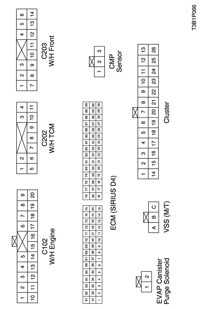
b. CONNECTOR IDENTIFICATION SYMBOL & PIN NUMBER POSITION
c. POSITION OF CONNECTORS AND GROUNDS
d. SPLICE PACK
s101
s201
s202
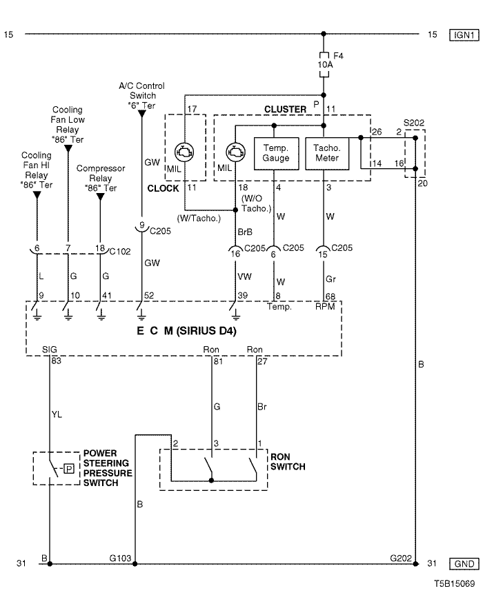
6) cluster, power steering pressure switch & ron switch circuit
a. CONNECTOR INFORMATION
connector no
(pin no, color) | connecting wiring harness | connector position |
| C102 (20 Pin, White) | Engine – Front | Engine Room Fuse Block |
| C205 (18 Pin, Gray) | IP – Engine | Behind I/P Fuse Block |
| G103 | Engine | Next to #4 Injector |
| G202 | IP | Behind Right Ashtray |
b. CONNECTOR IDENTIFICATION SYMBOL & PIN NUMBER POSITION
c. POSITION OF CONNECTORS AND GROUNDS
d. SPLICE PACK
s202
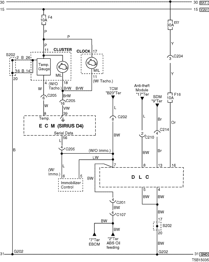
7) mil lamp & dlc (data link connector) circuit
a. CONNECTOR INFORMATION
connector no
(pin no, color) | connecting wiring harness | connector position |
| C107 (10 Pin, Black) | Front – Body | Behind Left A Pillar |
| C201 (18 Pin, Blue) | Body – IP | Under I/P Fuse Block |
| C202 (11 Pin, White) | TCM – IP | Behind I/P Fuse Block |
| C204 (4 Pin, White) | Front – IP | Under I/P Fuse Block |
| C205 (18 Pin, Gray) | IP – Engine | Behind I/P Fuse Block |
| C210 (8 Pin, Green) | IP – Body | Under Left A Pillar |
| C214 (4 Pin, White) | Air Bag - IP | Behind Audio |
| G202 | IP | Behind Right Ashtray |
b. CONNECTOR IDENTIFICATION SYMBOL & PIN NUMBER POSITION
c. POSITION OF CONNECTORS AND GROUNDS
d. SPLICE PACK
s202
sm