6. AIR CONDITIONER
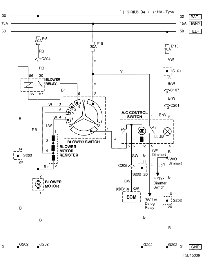
1) air conditioner control switch & blower motor circuit
a. CONNECTOR INFORMATION
connector no
(pin no, color) | connecting wiring harness | connector position |
| C107 (10 Pin, Black) | Front – Body | Behind Left A Pillar |
| C201 (18 Pin, Blue) | Body – IP | Under I/P Fuse Block |
| C204 (4 Pin, White) | Front – IP | Under I/P Fuse Block |
| C205 (18 Pin, Gray) | IP – Engine | Behind I/P Fuse Block |
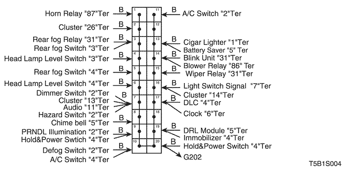
| G202 | IP | Behind Right Ashtray |
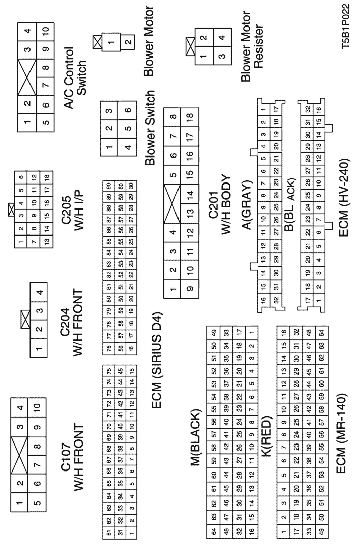
b. CONNECTOR IDENTIFICATION SYMBOL & PIN NUMBER POSITION
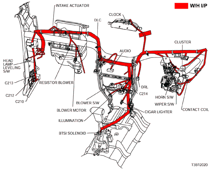
c. POSITION OF CONNECTORS AND GROUNDS
d. SPLICE PACK
s101
s202
2) a/c compressor & a/c control switch circuit
a. CONNECTOR INFORMATION
connector no
(pin no, color) | connecting wiring harness | connector position |
| C102 (20 Pin, White) | Engine – Front | Engine Room Fuse Block |
| C107 (10 Pin, Black) | Front – Body | Behind Left A Pillar |
| C201 (18 Pin, Blue) | Body – IP | Under I/P Fuse Block |
| C205 (18 Pin, Gray) | IP – Engine | Behind I/P Fuse Block |
| G102 | Front | Behind Left Head Lamp |
| G202 | IP | Behind Right Ashtray |
b. CONNECTOR IDENTIFICATION SYMBOL & PIN NUMBER POSITION
c. POSITION OF CONNECTORS AND GROUNDS
d. SPLICE PACK
s101
s202
sm