To the top of the document
Nubira-Lacetti
To Previous PageTo Next Page
GMDE Start PageLoad static TOCLoad dynamic TOCHelp?

SECTION 3

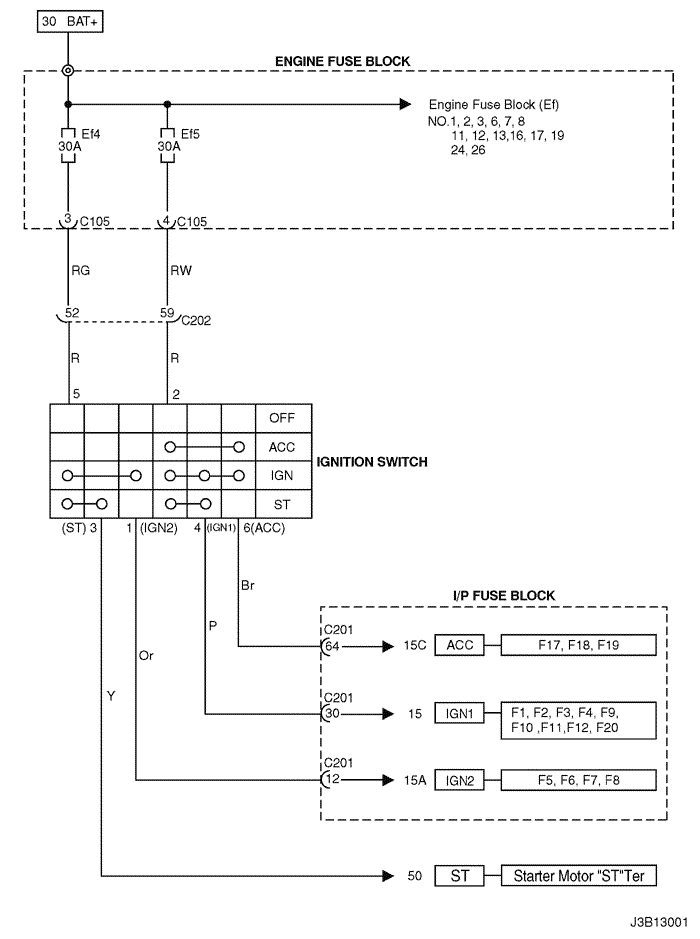
wiring diagram for power supplies


1. IGNITION SWITCH CIRCUIT

J3B13001.png
Display graphicTranslations of text in graphics


2. 30 TER "BAT+" POWER SUPPLY CIRCUIT (I.P FUSE BLOCK)

J3B13002.png
Display graphicTranslations of text in graphics


J5B13012.png
Display graphicTranslations of text in graphics


3. 15 TER "IGN1" POWER SUPPLY CIRCUIT (I.P FUSE BLOCK)

J5B13013.png
Display graphicTranslations of text in graphics


J5B13014.png
Display graphicTranslations of text in graphics


4. 15A TER "IGN2", 15C TER "ACC" POWER SUPPLY CIRCUIT (I.P FUSE BLOCK)

J5B13015.png
Display graphicTranslations of text in graphics


5. ENGINE FUSE BLOCK & RELAY CIRCUIT

J3D13004.png
Display graphicTranslations of text in graphics


J5B13016.png
Display graphicTranslations of text in graphics


J5B13017.png
Display graphicTranslations of text in graphics


J5B13018.png
Display graphicTranslations of text in graphics


J3B13024.png
Display graphicTranslations of text in graphics


J5B13019.png
Display graphicTranslations of text in graphics


J3D13008.png
Display graphicTranslations of text in graphics


J5B13020.png
Display graphicTranslations of text in graphics


J5B13021.png
Display graphicTranslations of text in graphics


J3D13011.png
Display graphicTranslations of text in graphics


J3D13012.png
Display graphicTranslations of text in graphics


J5B13022.png
Display graphicTranslations of text in graphics


J3D13014.png
Display graphicTranslations of text in graphics


sm
To Previous PageTo Next Page


pkfnpo.ru


Поиск по сайту

Карта сайта №1 Карта сайта №2