SECTION 5
electrical wiring diagrams
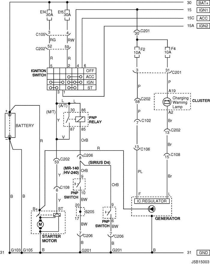
1. STARTING & CHARGING SYSTEM
1) battery, ignition switch, starter motor, generator & pnp switch circuit
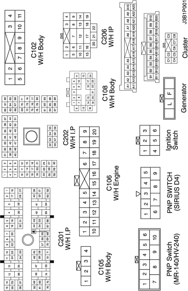
a. CONNECTOR INFORMATION
connector no
(pin no, color) | connecting wiring harness | connector position |
| C102 (11 Pin, White) | Body – Engine Fuse Block | Engine Fuse Block |
| C105 (4 Pin, White) | Body – Engine Fuse Block | Engine Fuse Block |
| C106 (20 Pin, White) | Engine – Engine Fuse Block | Engine Fuse Block |
| C108 (24 Pin, Black) | Body – Engine | Left Engine Fuse Block |
| C201 (76 Pin, Black) | I.P – I.P Fuse Block | I.P Fuse Block |
| C202 (89 Pin, White) | I.P – Body | Left CO-Driver Leg Room |
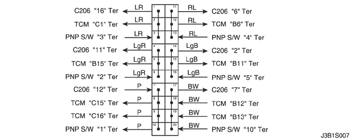
| C206 (22 Pin, White) | I.P – TCM | Upper Driver Leg Room |
| S205 (Orange) | TCM | Upper Driver Leg Room |
| G103 | Battery | Left Battery |
| G105 | Battery | Under Start Motor |
| G201 | I.P | Left I.P Fuse Block |
b. CONNECTOR IDENTIFICATION SYMBOL & PIN NUMBER POSITION
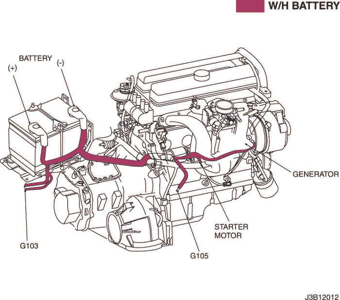
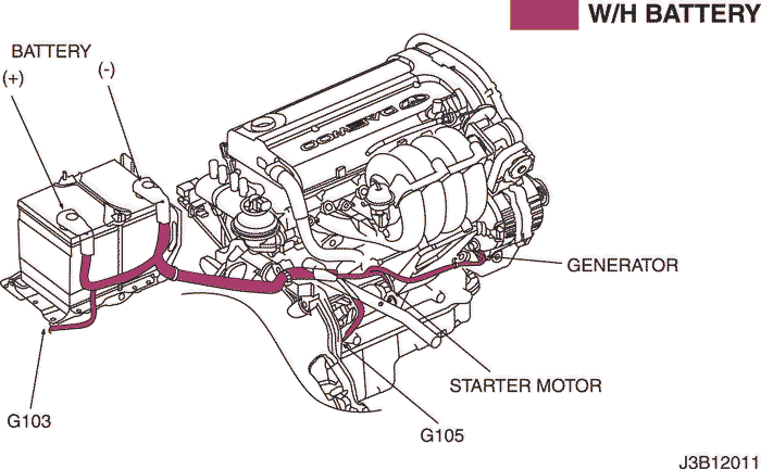
c. POSITION OF CONNECTORS AND GROUNDS
mr-140/hv-240
sirius d4
d. SPLICE PACK
s205 : mr-140/hv-240
sm