|
Nubira-Lacetti
|
||||||||
|
|
|||||||

|
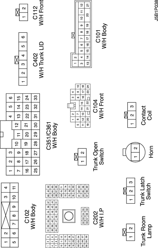
CONNECTOR NO (PIN NO, COLOR) |
CONNECTING WIRING HARNESS | CONNECTOR POSITION |
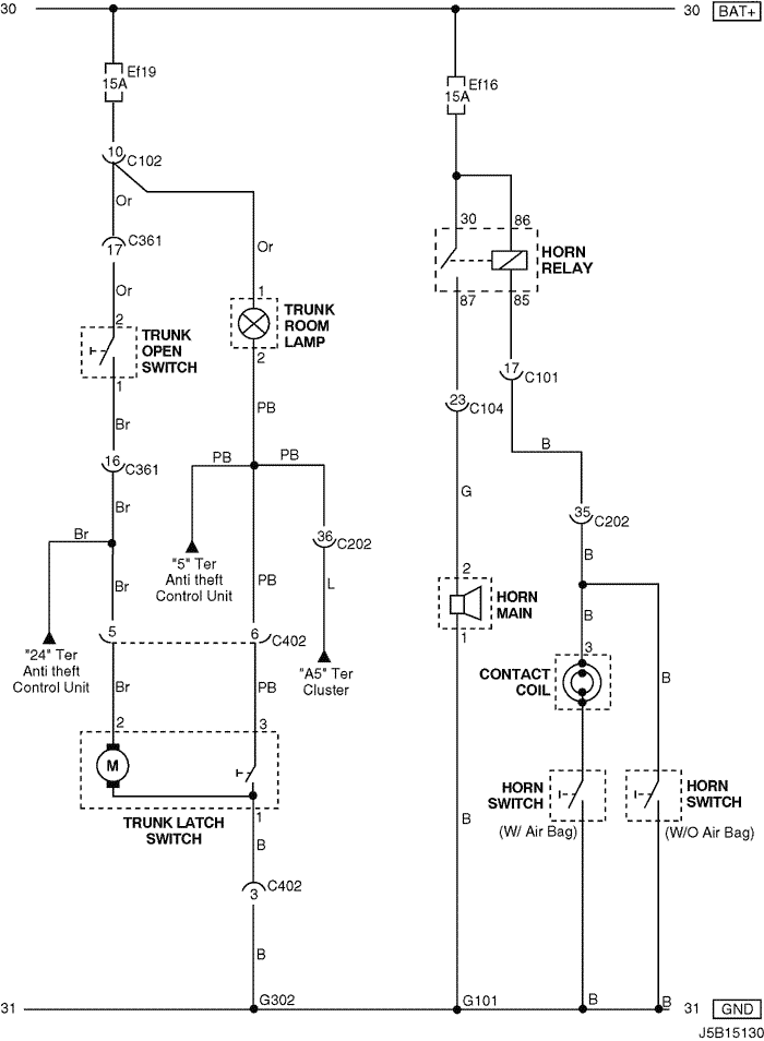
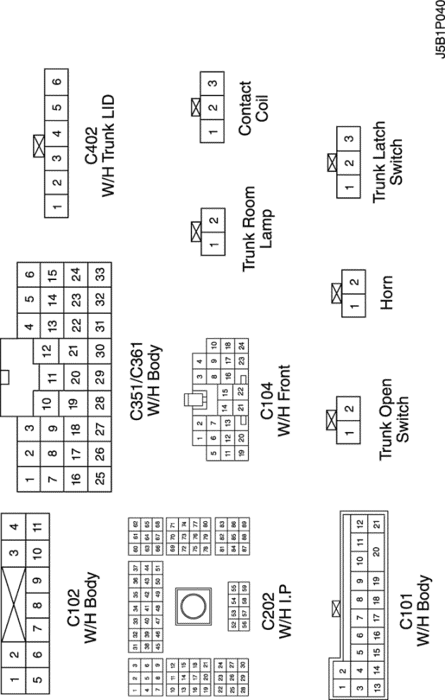
| C101 (21 Pin, White) | Body – Engine Fuse Block | Engine Fuse Block |
| C102 (11 Pin, White) | Body – Engine Fuse Block | Engine Fuse Block |
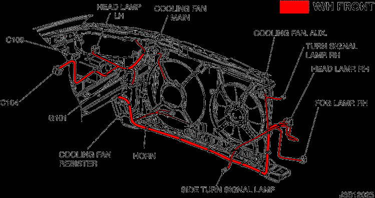
| C104 (24 Pin, White) | Front – Engine Fuse Block | Engine Fuse Block |
| C112 (2 Pin, Black) | Front – Horn | Center Cross Member Panel |
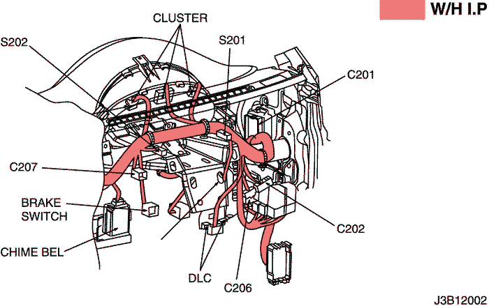
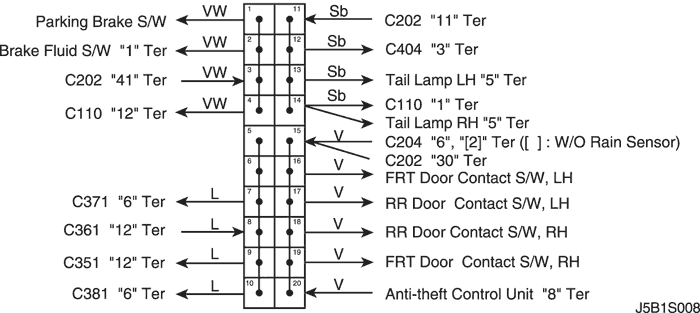
| C202 (89 Pin, White) | I.P – Body | Left CO-Driver Leg Room |
| C361 (33 Pin, Gray) | Body – Front Right Door | Under Driver A Pillar |
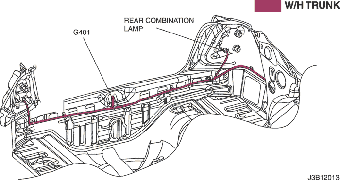
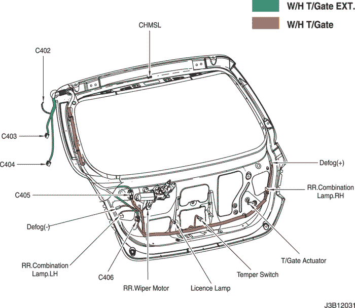
| C402 (8 Pin, White) | Trunk LID – Body | Inside Right Trunk Side Cover |
| G101 | Front | Behind Left Head Lamp |
| G302 | Body | Below Left C Pillar |

|
CONNECTOR NO (PIN NO, COLOR) |
CONNECTING WIRING HARNESS | CONNECTOR POSITION |
| C101 (21 Pin, White) | Body – Engine Fuse Block | Engine Fuse Block |
| C102 (11 Pin, White) | Body – Engine Fuse Block | Engine Fuse Block |
| C104 (24 Pin, White) | Front – Engine Fuse Block | Engine Fuse Block |
| C202 (89 Pin, White) | I.P – Body | Left CO-Driver Leg Room |
| C361 (33 Pin, Gray) | Body – Front Right Door | Under Driver A Pillar |
| C402 (8 Pin, White) | Trunk LID – Body | Inside Right Trunk Side Cover |
| G101 | Front | Behind Left Head Lamp |
| G302 | Body | Below Left C Pillar |
|
CONNECTOR NO (PIN NO, COLOR) |
CONNECTING WIRING HARNESS | CONNECTOR POSITION |
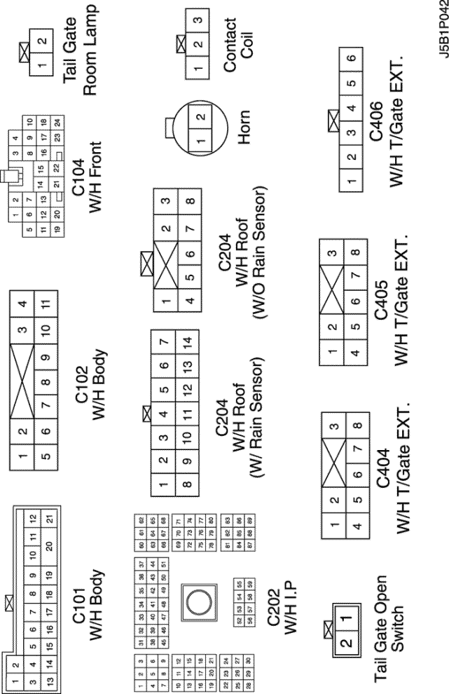
| C101 (21 Pin, White) | Body – Engine Fuse Block | Engine Fuse Block |
| C102 (11 Pin, White) | Body – Engine Fuse Block | Engine Fuse Block |
| C104 (24 Pin, White) | Front – Engine Fuse Block | Engine Fuse Block |
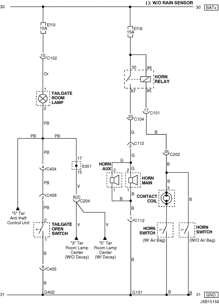
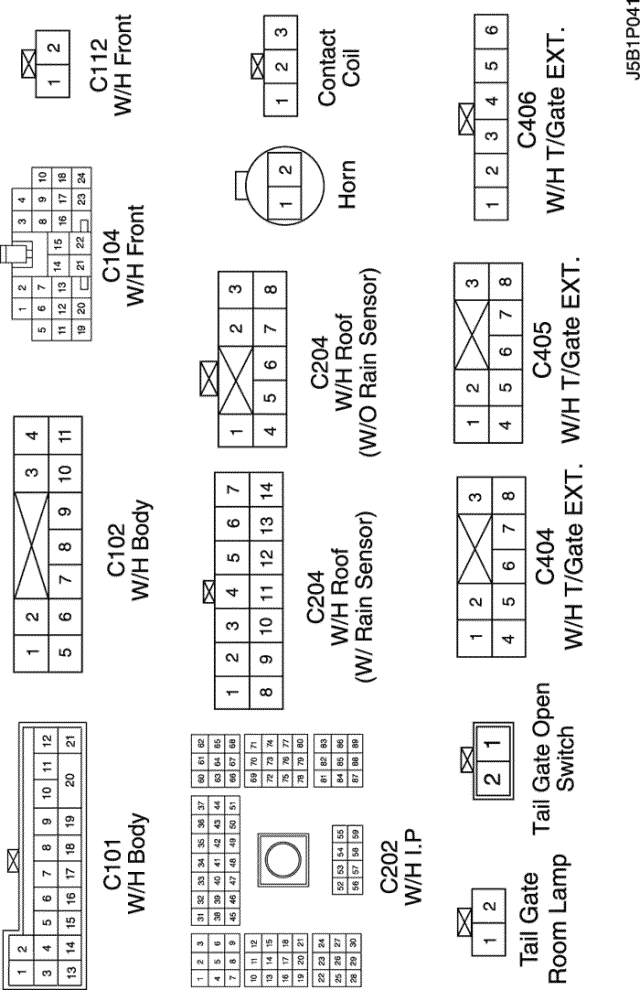
| C112 (2 Pin, Black) | Front – Horn | Center Cross Member Panel |
| C202 (89 Pin, White) | I.P – Body | Left CO-Driver Leg Room |
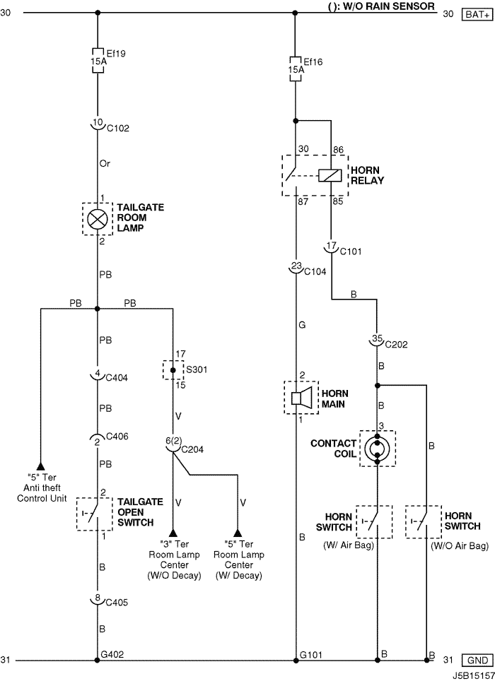
| C204 (8 Pin, White) | Roof - Body (W/O Rain Sensor) | Left CO-Driver Leg Room |
| C204 (14 Pin, White) | Roof - Body (W/ Rain Sensor) | Left CO-Driver Leg Room |
| C404 (8 Pin, White) | T/Gate. EXT. – Body | Inside Left C Pillar |
| C405 (8 Pin, White) | T/Gate. EXT. – T/Gate | Beside Left Rear Wiper Motor |
| C406 (6 Pin, White) | T/Gate. EXT. – T/Gate | Beside Left Rear Wiper Motor |
| S301 (Blue) | Body | Left CO-Driver Leg Room |
| G101 | Front | Behind Left Head Lamp |
| G402 | T/Gate. EXT | Inside Driver C Pillar |

|
CONNECTOR NO (PIN NO, COLOR) |
CONNECTING WIRING HARNESS | CONNECTOR POSITION |
| C101 (21 Pin, White) | Body – Engine Fuse Block | Engine Fuse Block |
| C102 (11 Pin, White) | Body – Engine Fuse Block | Engine Fuse Block |
| C104 (24 Pin, White) | Front – Engine Fuse Block | Engine Fuse Block |
| C202 (89 Pin, White) | I.P – Body | Left CO-Driver Leg Room |
| C204 (8 Pin, White) | Roof - Body (W/O Rain Sensor) | Left CO-Driver Leg Room |
| C204 (14 Pin, White) | Roof - Body (W/ Rain Sensor) | Left CO-Driver Leg Room |
| C404 (8 Pin, White) | T/Gate. EXT. – Body | Inside Left C Pillar |
| C405 (8 Pin, White) | T/Gate. EXT. – T/Gate | Beside Left Rear Wiper Motor |
| C406 (6 Pin, White) | T/Gate. EXT. – T/Gate | Beside Left Rear Wiper Motor |
| S301 (Blue) | Body | Left CO-Driver Leg Room |
| G101 | Front | Behind Left Head Lamp |
| G402 | T/Gate. EXT | Inside Driver C Pillar |
|
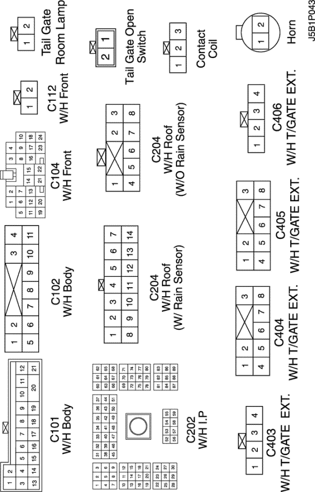
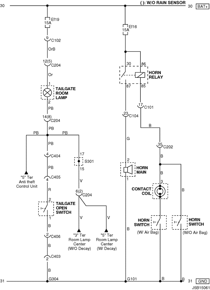
CONNECTOR NO (PIN NO, COLOR) |
CONNECTING WIRING HARNESS | CONNECTOR POSITION |
| C101 (21 Pin, White) | Body – Engine Fuse Block | Engine Fuse Block |
| C102 (11 Pin, White) | Body – Engine Fuse Block | Engine Fuse Block |
| C104 (24 Pin, White) | Front – Engine Fuse Block | Engine Fuse Block |
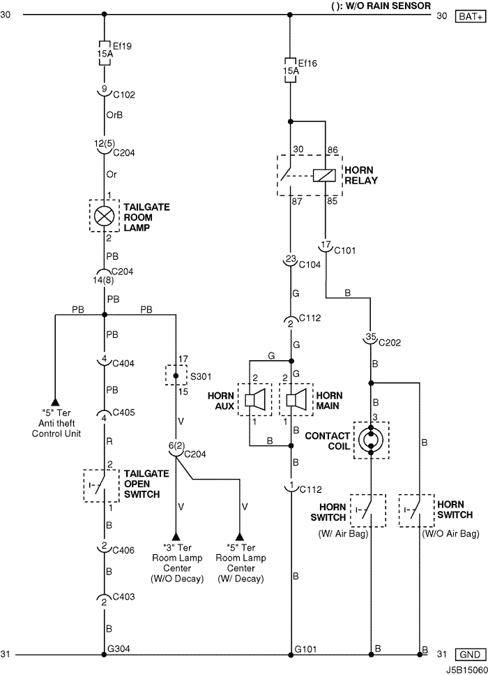
| C112 (2 Pin, Black) | Front – Horn | Center Cross Member Panel |
| C202 (89 Pin, White) | I.P – Body | Left CO-Driver Leg Room |
| C204 (8 Pin, White) | Roof - Body (W/O Rain Sensor) | Left CO-Driver Leg Room |
| C204 (14 Pin, White) | Roof - Body (W/ Rain Sensor) | Left CO-Driver Leg Room |
| C403 (4 Pin, White) | T/Gate. EXT. - Body | Inside Left C Pillar |
| C404 (8 Pin, White) | T/Gate. EXT. - Body | Inside Left C Pillar |
| C405 (8 Pin, White) | T/Gate. EXT. - T/Gate | Beside Left Rear Wiper Motor |
| C406 (4 Pin, White) | T/Gate. EXT. - T/Gate | Beside Left Rear Wiper Motor |
| S301 (Blue) | Body | Left CO-Driver Leg Room |
| G101 | Front | Behind Left Head Lamp |
| G304 | Body | Below Left Rear Combination Lamp |
|
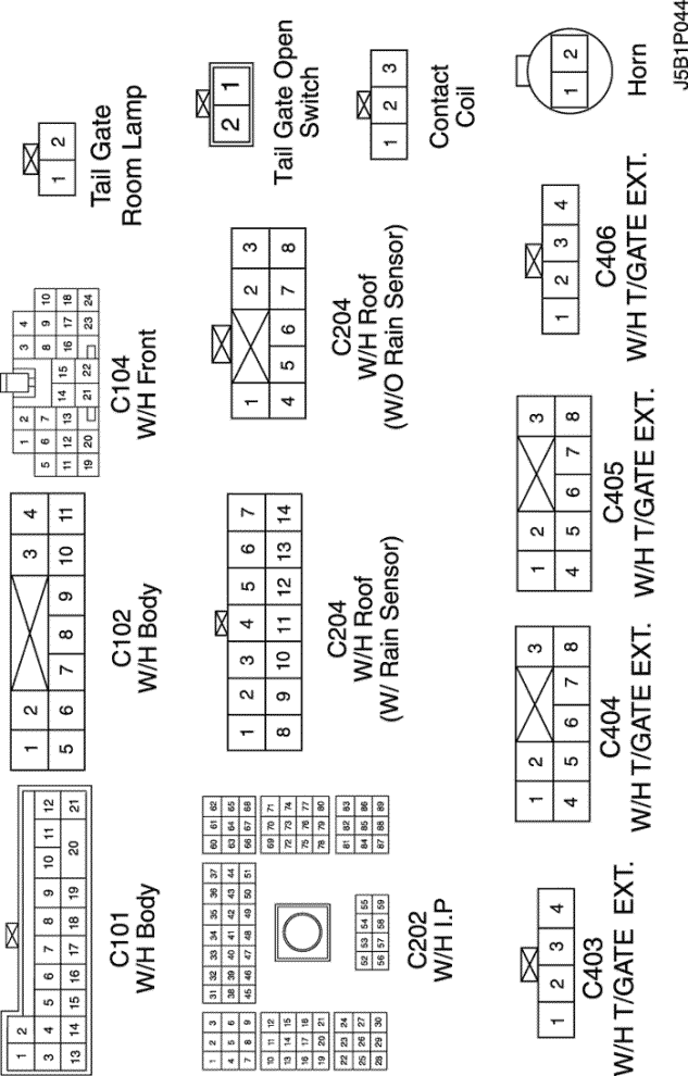
CONNECTOR NO (PIN NO, COLOR) |
CONNECTING WIRING HARNESS | CONNECTOR POSITION |
| C101 (21 Pin, White) | Body – Engine Fuse Block | Engine Fuse Block |
| C102 (11 Pin, White) | Body – Engine Fuse Block | Engine Fuse Block |
| C104 (24 Pin, White) | Front – Engine Fuse Block | Engine Fuse Block |
| C202 (89 Pin, White) | I.P – Body | Left CO-Driver Leg Room |
| C204 (8 Pin, White) | Roof - Body (W/O Rain Sensor) | Left CO-Driver Leg Room |
| C204 (14 Pin, White) | Roof - Body (W/ Rain Sensor) | Left CO-Driver Leg Room |
| C403 (4 Pin, White) | T/Gate. EXT. - Body | Inside Left C Pillar |
| C404 (8 Pin, White) | T/Gate. EXT. - Body | Inside Left C Pillar |
| C405 (8 Pin, White) | T/Gate. EXT. - T/Gate | Beside Left Rear Wiper Motor |
| C406 (4 Pin, White) | T/Gate. EXT. - T/Gate | Beside Left Rear Wiper Motor |
| S301 (Blue) | Body | Left CO-Driver Leg Room |
| G101 | Front | Behind Left Head Lamp |
| G304 | Body | Below Left Rear Combination Lamp |
sm
|
|
|
| © Copyright Chevrolet Europe. All rights reserved |


