|
Nubira-Lacetti
|
||||||||
|
|
|||||||
|
CONNECTOR NO (PIN NO, COLOR) |
CONNECTING WIRING HARNESS | CONNECTOR POSITION |
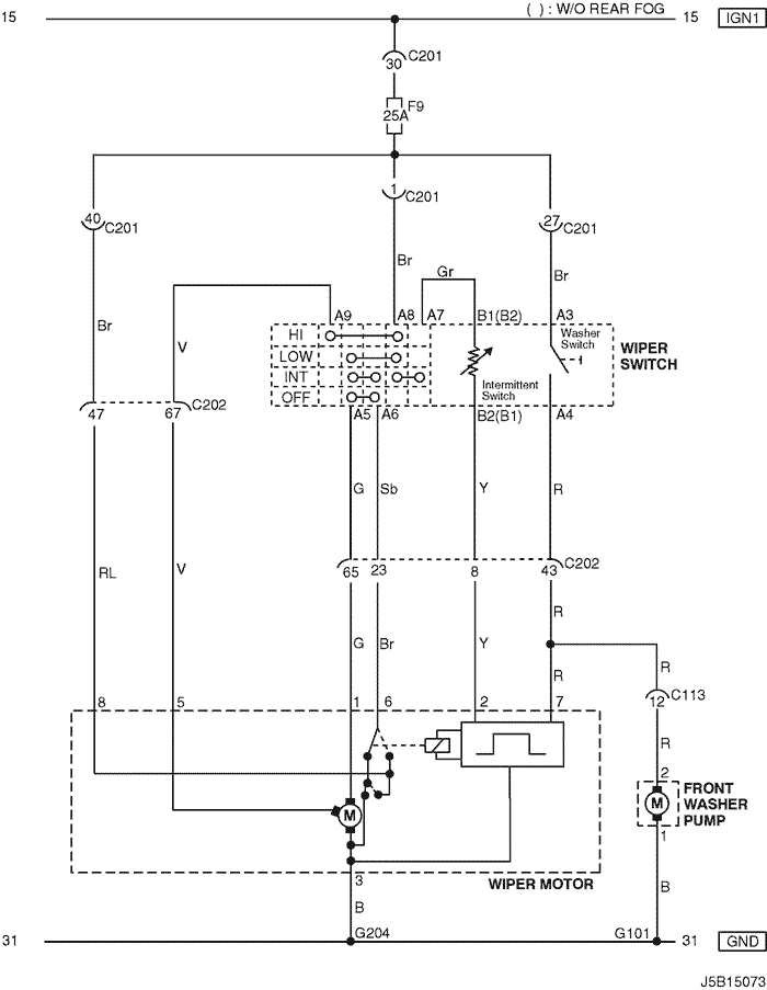
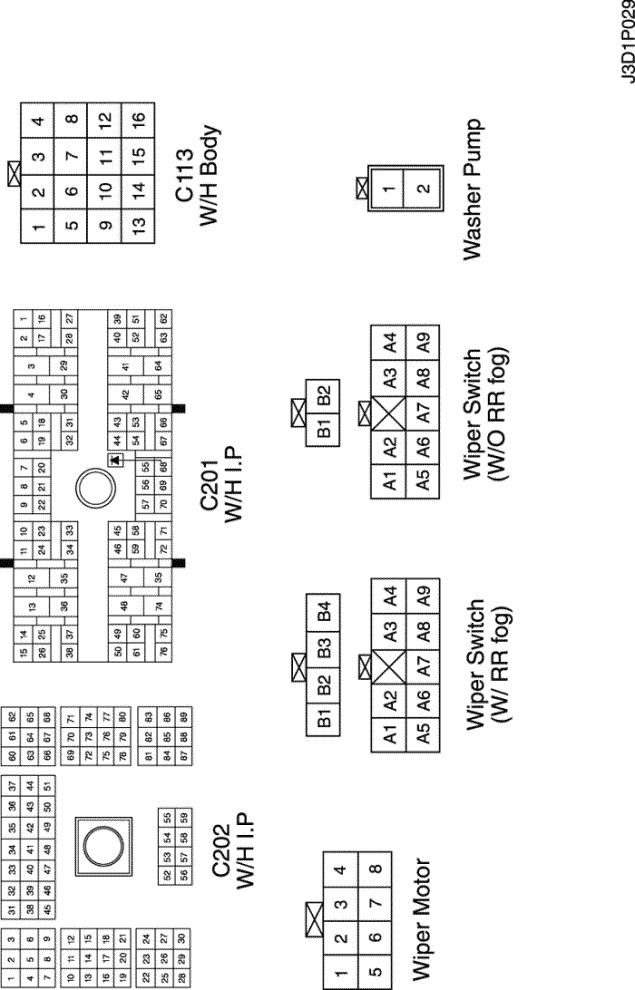
| C113 (16 Pin, Black) | Body – Front | Behind ECM Bracket |
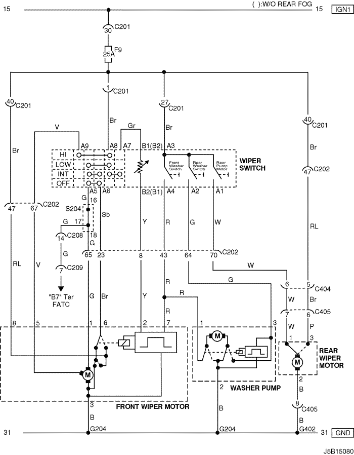
| C201 (76 Pin, Black) | I.P – I.P Fuse Block | I.P Fuse Block |
| C202 (89 Pin, White) | I.P – Body | Left CO-Driver Leg Room |
| G101 | Front | Behind Left Head Lamp |
| G204 | Body | Below Left CO-Driver Leg Room |
|
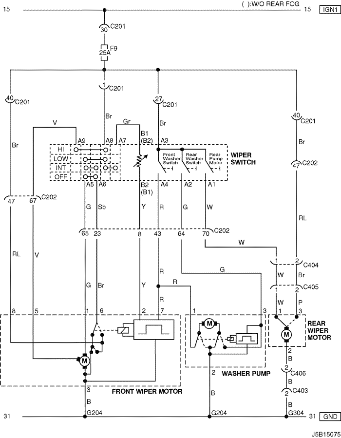
CONNECTOR NO (PIN NO, COLOR) |
CONNECTING WIRING HARNESS | CONNECTOR POSITION |
| C201 (76 Pin, Black) | I.P – I.P Fuse Block | I.P Fuse Block |
| C202 (89 Pin, White) | I.P – Body | Left CO-Driver Leg Room |
| C404 (8 Pin, White) | T/Gate. EXT. – Body | Inside Left C Pillar |
| C405 (8 Pin, White) | T/Gate. EXT. – T/Gate | Beside Left Rear Wiper Motor |
| G204 | Body | Below Left CO-Driver Leg Room |
| G402 | T/Gate. EXT. | Inside Driver C Pillar |
|
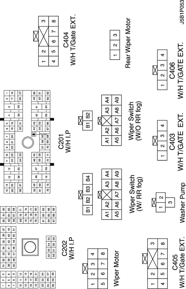
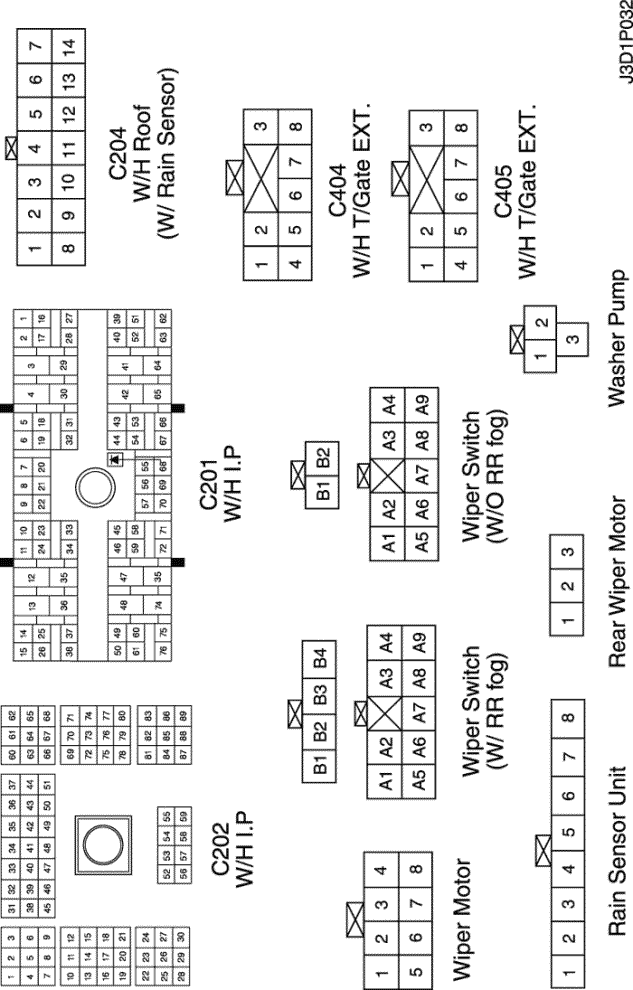
CONNECTOR NO (PIN NO, COLOR) |
CONNECTING WIRING HARNESS | CONNECTOR POSITION |
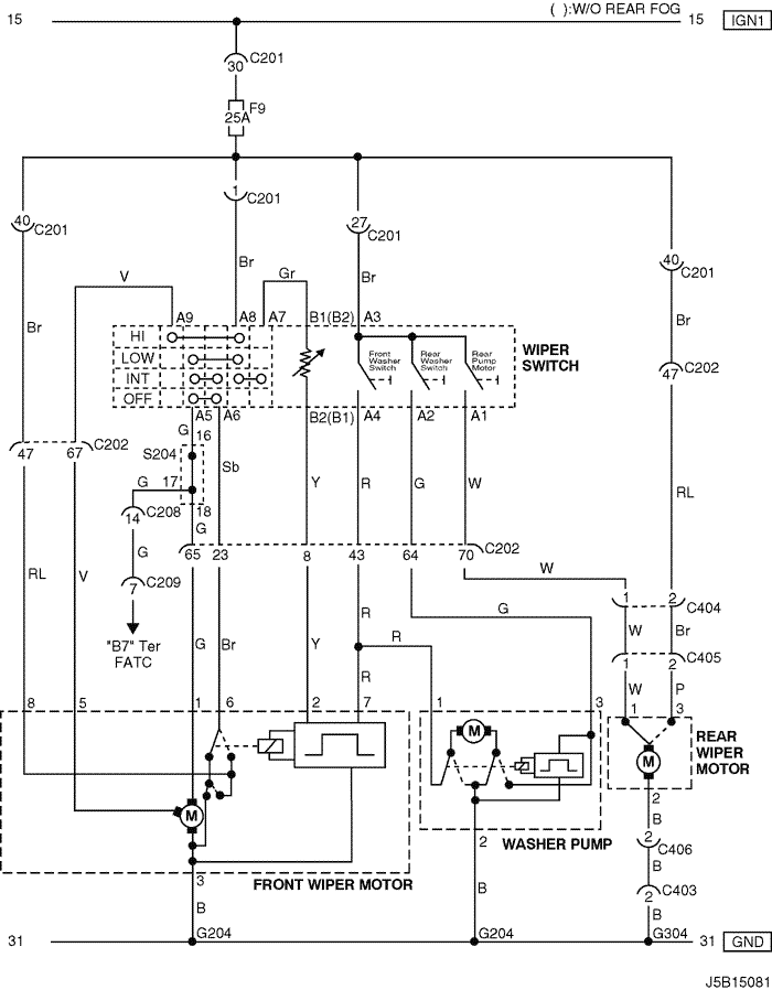
| C201 (76 Pin, Black) | I.P – I.P Fuse Block | I.P Fuse Block |
| C202 (89 Pin, White) | I.P – Body | Left CO-Driver Leg Room |
| C403 (4 Pin, White) | T/Gate. EXT. - Body | Inside Left C Pillar |
| C404 (8 Pin, White) | T/Gate. EXT. – Body | Inside Left C Pillar |
| C405 (8 Pin, White) | T/Gate. EXT. – T/Gate | Beside Left Rear Wiper Motor |
| C406 (4 Pin, White) | T/Gate. EXT. - T/Gate | Beside Left Rear Wiper Motor |
| G204 | Body | Below Left CO-Driver Leg Room |
| G304 | Body | Below Left Rear Combination Lamp |

|
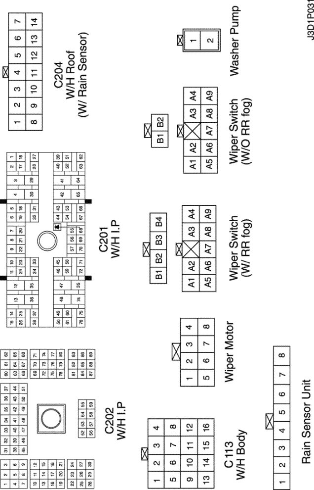
CONNECTOR NO (PIN NO, COLOR) |
CONNECTING WIRING HARNESS | CONNECTOR POSITION |
| C113 (16 Pin, Black) | Body – Front | Behind ECM Bracket |
| C201 (76 Pin, Black) | I.P – I.P Fuse Block | I.P Fuse Block |
| C202 (89 Pin, White) | I.P – Body | Left CO-Driver Leg Room |
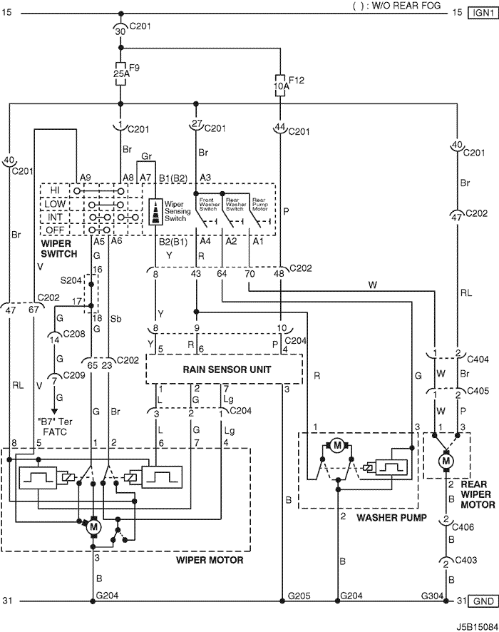
| C204 (14 Pin, White) | Roof – Body (W/ Rain Sensor) | Left CO-Driver Leg Room |
| C204 (8 Pin, White) | Roof – Body (W/O Rain Sensor) | Left CO-Driver Leg Room |
| G101 | Front | Behind Left Head Lamp |
| G204 | Body | Below Left CO-Driver Leg Room |
| G205 | Roof | Inside CO-Driver A Pillar |
|
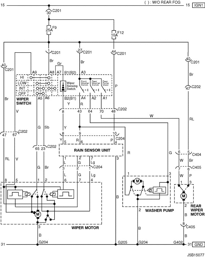
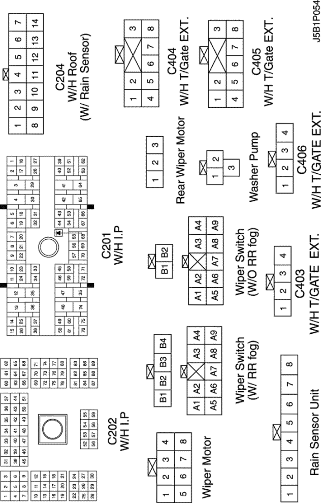
CONNECTOR NO (PIN NO, COLOR) |
CONNECTING WIRING HARNESS | CONNECTOR POSITION |
| C201 (76 Pin, Black) | I.P – I.P Fuse Block | I.P Fuse Block |
| C202 (89 Pin, White) | I.P – Body | Left CO-Driver Leg Room |
| C204 (14 Pin, White) | Roof – Body (W/ Rain Sensor) | Left CO-Driver Leg Room |
| C204 (8 Pin, White) | Roof – Body (W/O Rain Sensor) | Left CO-Driver Leg Room |
| C404 (8 Pin, White) | T/Gate. EXT. – Body | Inside Left C Pillar |
| C405 (8 Pin, White) | T/Gate. EXT. – T/Gate | Beside Left Rear Wiper Motor |
| G204 | Body | Below Left CO-Driver Leg Room |
| G205 | Roof | Inside CO-Driver A Pillar |
| G402 | T/Gate. EXT. | Inside Driver C Pillar |
|
CONNECTOR NO (PIN NO, COLOR) |
CONNECTING WIRING HARNESS | CONNECTOR POSITION |
| C201 (76 Pin, Black) | I.P – I.P Fuse Block | I.P Fuse Block |
| C202 (89 Pin, White) | I.P – Body | Left CO-Driver Leg Room |
| C204 (14 Pin, White) | Roof – Body (W/ Rain Sensor) | Left CO-Driver Leg Room |
| C204 (8 Pin, White) | Roof – Body (W/O Rain Sensor) | Left CO-Driver Leg Room |
| C403 (4 Pin, White) | T/Gate. EXT. - Body | Inside Left C Pillar |
| C404 (8 Pin, White) | T/Gate. EXT. – Body | Inside Left C Pillar |
| C405 (8 Pin, White) | T/Gate. EXT. – T/Gate | Beside Left Rear Wiper Motor |
| C406 (4 Pin, White) | T/Gate. EXT. - T/Gate | Beside Left Rear Wiper Motor |
| G204 | Body | Below Left CO-Driver Leg Room |
| G205 | Roof | Inside CO-Driver A Pillar |
| G304 | Body | Below Left Rear Combination Lamp |

|
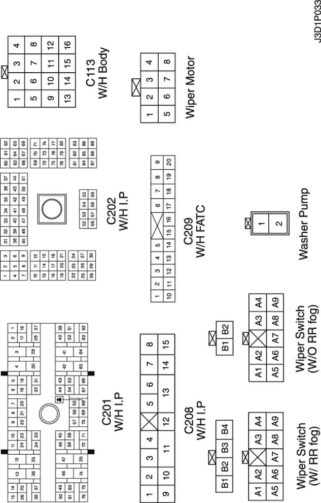
CONNECTOR NO (PIN NO, COLOR) |
CONNECTING WIRING HARNESS | CONNECTOR POSITION |
| C113 (16 Pin, Black) | Body – Front | Behind ECM Bracket |
| C201 (76 Pin, Black) | I.P – I.P Fuse Block | I.P Fuse Block |
| C202 (89 Pin, White) | I.P – Body | Left CO-Driver Leg Room |
| C208 (15 Pin, White) | I.P – FATC | Behind Glove Box |
| C209 (20 Pin, Black) | FATC – FATC.Aux | Between Heater Core and Evaporator Core |
| S204 (Magenta) | I.P | Behind Audio Mounting |
| G101 | Front | Behind Left Head Lamp |
| G204 | Body | Below Left CO-Driver Leg Room |

|
CONNECTOR NO (PIN NO, COLOR) |
CONNECTING WIRING HARNESS | CONNECTOR POSITION |
| C201 (76 Pin, Black) | I.P – I.P Fuse Block | I.P Fuse Block |
| C202 (89 Pin, White) | I.P – Body | Left CO-Driver Leg Room |
| C208 (15 Pin, White) | I.P – FATC | Behind Glove Box |
| C209 (20 Pin, Black) | FATC – FATC.Aux | Between Heater Core and Evaporator Core |
| C404 (8 Pin, White) | T/Gate. EXT. – Body | Inside Left C Pillar |
| C405 (8 Pin, White) | T/Gate. EXT. – T/Gate | Beside Left Rear Wiper Motor |
| S204 (Magenta) | I.P | Behind Audio Mounting |
| G204 | Body | Below Left CO-Driver Leg Room |
| G402 | T/Gate. EXT. | Inside Driver C Pillar |

|
CONNECTOR NO (PIN NO, COLOR) |
CONNECTING WIRING HARNESS | CONNECTOR POSITION |
| C201 (76 Pin, Black) | I.P – I.P Fuse Block | I.P Fuse Block |
| C202 (89 Pin, White) | I.P – Body | Left CO-Driver Leg Room |
| C208 (15 Pin, White) | I.P – FATC | Behind Glove Box |
| C209 (20 Pin, Black) | FATC – FATC.Aux | Between Heater Core and Evaporator Core |
| C403 (4 Pin, White) | T/Gate. EXT. - Body | Inside Left C Pillar |
| C404 (8 Pin, White) | T/Gate. EXT. – Body | Inside Left C Pillar |
| C405 (8 Pin, White) | T/Gate. EXT. – T/Gate | Beside Left Rear Wiper Motor |
| C406 (4 Pin, White) | T/Gate. EXT. - T/Gate | Beside Left Rear Wiper Motor |
| S204 (Magenta) | I.P | Behind Audio Mounting |
| G204 | Body | Below Left CO-Driver Leg Room |
| G304 | Body | Below Left Rear Combination Lamp |

|
CONNECTOR NO (PIN NO, COLOR) |
CONNECTING WIRING HARNESS | CONNECTOR POSITION |
| C113 (16 Pin, Black) | Body – Front | Behind ECM Bracket |
| C201 (76 Pin, Black) | I.P – I.P Fuse Block | I.P Fuse Block |
| C202 (89 Pin, White) | I.P – Body | Left CO-Driver Leg Room |
| C204 (14 Pin, White) | Roof – Body (W/ Rain Sensor) | Left CO-Driver Leg Room |
| C204 (8 Pin, White) | Roof – Body (W/O Rain Sensor) | Left CO-Driver Leg Room |
| C208 (15 Pin, White) | I.P – FATC | Behind Glove Box |
| C209 (20 Pin, Black) | FATC – FATC.Aux | Between Heater Core and Evaporator Core |
| S204 (Magenta) | I.P | Behind Audio Mounting |
| G101 | Front | Behind Left Head Lamp |
| G204 | Body | Below Left CO-Driver Leg Room |
| G205 | Roof | Inside CO-Driver A Pillar |


|
CONNECTOR NO (PIN NO, COLOR) |
CONNECTING WIRING HARNESS | CONNECTOR POSITION |
| C201 (76 Pin, Black) | I.P – I.P Fuse Block | I.P Fuse Block |
| C202 (89 Pin, White) | I.P – Body | Left CO-Driver Leg Room |
| C204 (14 Pin, White) | Roof – Body (W/ Rain Sensor) | Left CO-Driver Leg Room |
| C204 (8 Pin, White) | Roof – Body (W/O Rain Sensor) | Left CO-Driver Leg Room |
| C208 (15 Pin, White) | I.P – FATC | Behind Glove Box |
| C209 (20 Pin, Black) | FATC – FATC.Aux | Between Heater Core and Evaporator Core |
| C404 (8 Pin, White) | T/Gate. EXT. – Body | Inside Left C Pillar |
| C405 (8 Pin, White) | T/Gate. EXT. – T/Gate | Beside Left Rear Wiper Motor |
| S204 (Magenta) | I.P | Behind Audio Mounting |
| G204 | Body | Below Left CO-Driver Leg Room |
| G205 | Roof | Inside CO-Driver A Pillar |
| G402 | T/Gate. EXT. | Inside Driver C Pillar |

|
CONNECTOR NO (PIN NO, COLOR) |
CONNECTING WIRING HARNESS | CONNECTOR POSITION |
| C201 (76 Pin, Black) | I.P – I.P Fuse Block | I.P Fuse Block |
| C202 (89 Pin, White) | I.P – Body | Left CO-Driver Leg Room |
| C204 (14 Pin, White) | Roof – Body (W/ Rain Sensor) | Left CO-Driver Leg Room |
| C204 (8 Pin, White) | Roof – Body (W/O Rain Sensor) | Left CO-Driver Leg Room |
| C208 (15 Pin, White) | I.P – FATC | Behind Glove Box |
| C209 (20 Pin, Black) | FATC – FATC.Aux | Between Heater Core and Evaporator Core |
| C403 (4 Pin, White) | T/Gate. EXT. - Body | Inside Left C Pillar |
| C404 (8 Pin, White) | T/Gate. EXT. – Body | Inside Left C Pillar |
| C405 (8 Pin, White) | T/Gate. EXT. – T/Gate | Beside Left Rear Wiper Motor |
| C406 (4 Pin, White) | T/Gate. EXT. - T/Gate | Beside Left Rear Wiper Motor |
| S204 (Magenta) | I.P | Behind Audio Mounting |
| G204 | Body | Below Left CO-Driver Leg Room |
| G205 | Roof | Inside CO-Driver A Pillar |
| G304 | Body | Below Left Rear Combination Lamp |

sm
|
|
|
| © Copyright Chevrolet Europe. All rights reserved |


