|
Nubira-Lacetti
|
||||||||
|
|
|||||||

|
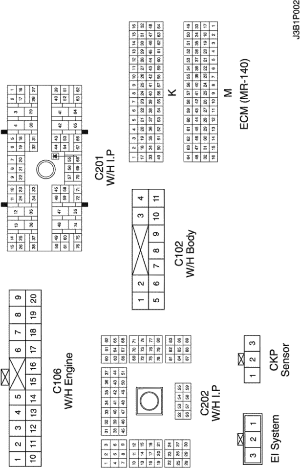
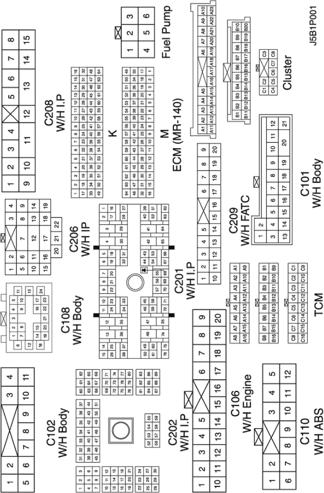
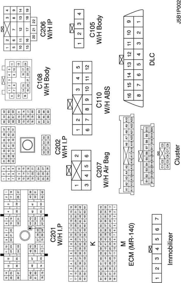
CONNECTOR NO (PIN NO, COLOR) |
CONNECTING WIRING HARNESS | CONNECTOR POSITION |
| C102 (11 Pin, White) | Body – Engine Fuse Block | Engine Fuse Block |
| C106 (20 Pin, White) | Engine – Engine Fuse Block | Engine Fuse Block |
| C201 (76 Pin, Black) | I.P – I.P Fuse Block | I.P Fuse Block |
| C202 (89 Pin, White) | I.P – Body | Left CO-Driver Leg Room |
| S101 (Black) | Engine (MR-140/HV-240) | Upper Transmission |
| G104 | Engine | Under Start Motor |
| G107 | Engine (MR-140/HV-240) | Under Start Motor |
|
CONNECTOR NO (PIN NO, COLOR) |
CONNECTING WIRING HARNESS | CONNECTOR POSITION |
| C101 (21 Pin, White) | Body – Engine Fuse Block | Engine Fuse Block |
| C102 (11 Pin, White) | Body – Engine Fuse Block | Engine Fuse Block |
| C103 (10 Pin, White) | Engine – Engine Fuse Block | Engine Fuse Block |
| C106 (20 Pin, White) | Engine – Engine Fuse Block | Engine Fuse Block |
| C109 (4 Pin, White) | Engine – Front | Under Engine Fuse Block |
| C201 (76 Pin, Black) | I.P – I.P Fuse Block | I.P Fuse Block |
| C202 (89 Pin, White) | I.P – Body | Left CO-Driver Leg Room |
| G107 | Engine (MR-140/HV-240) | Under Start Motor |
| G302 | Body | Below Left C Pillar |
|
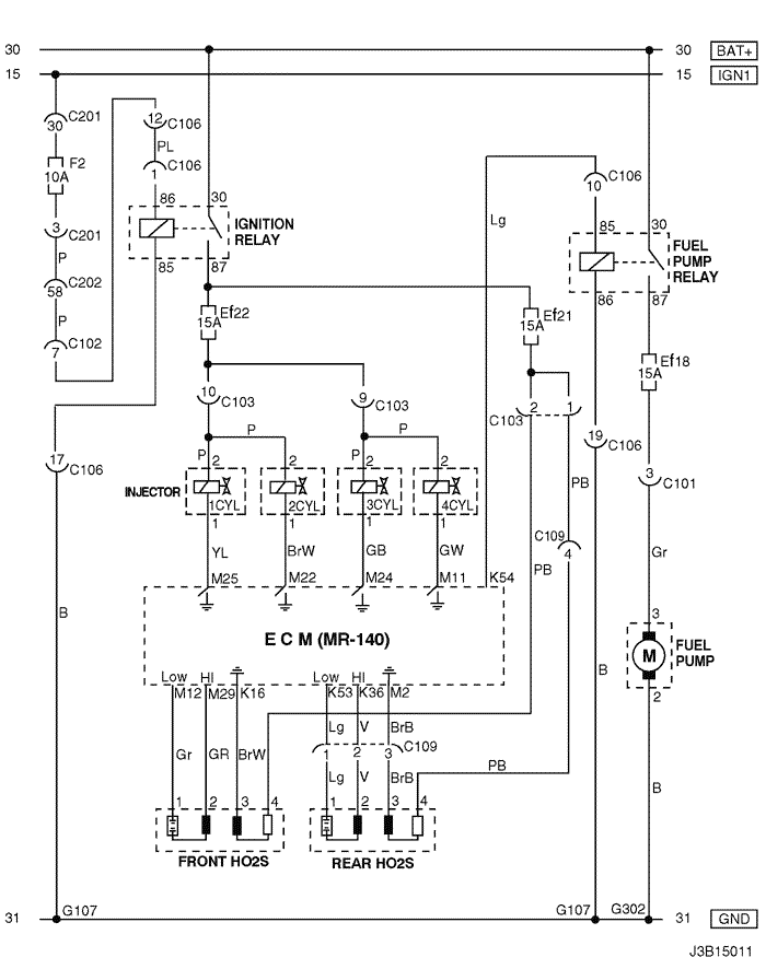
CONNECTOR NO (PIN NO, COLOR) |
CONNECTING WIRING HARNESS | CONNECTOR POSITION |
| C106 (20 Pin, White) | Engine – Engine Fuse Block | Engine Fuse Block |
| S101 (Black) | Engine (MR-140/HV-240) | Upper Transmission |
| G107 | Engine (MR-140/HV-240) | Under Start Motor |
|
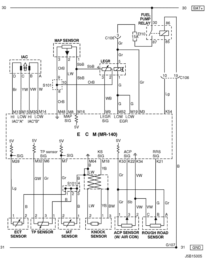
CONNECTOR NO (PIN NO, COLOR) |
CONNECTING WIRING HARNESS | CONNECTOR POSITION |
| C102 (11 Pin, White) | Body – Engine Fuse Block | Engine Fuse Block |
| C103 (10 Pin, White) | Engine – Engine Fuse Block | Engine Fuse Block |
| C106 (20 Pin, White) | Engine – Engine Fuse Block | Engine Fuse Block |
| C108 (24 Pin, Black) | Body – Engine | Left Engine Fuse Block |
| C113 (16 Pin, Black) | Body – Front | Behind ECM Bracket |
| C201 (76 Pin, Black) | I.P – I.P Fuse Block | I.P Fuse Block |
| C202 (89 Pin, White) | I.P – Body | Left CO-Driver Leg Room |
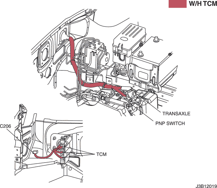
| C206 (22 Pin, White) | I.P – TCM | Upper Driver Leg Room |
| S202 (Black) | I.P | Behind Cluster |
| G104 | Engine | Under Start Motor |
| G107 | Engine (MR-140/HV-240) | Under Start Motor |
| G201 | I.P | Left I.P Fuse Block |
|
CONNECTOR NO (PIN NO, COLOR) |
CONNECTING WIRING HARNESS | CONNECTOR POSITION |
| C101 (21 Pin, White) | Body – Engine Fuse Block | Engine Fuse Block |
| C102 (11 Pin, White) | Body – Engine Fuse Block | Engine Fuse Block |
| C106 (20 Pin, White) | Engine – Engine Fuse Block | Engine Fuse Block |
| C108 (24 Pin, Black) | Body – Engine | Left Engine Fuse Block |
| C110 (12 Pin, White) | ABS – Body | Below Engine Fuse Block |
| C201 (76 Pin, Black) | I.P – I.P Fuse Block | I.P Fuse Block |
| C202 (89 Pin, White) | I.P – Body | Left CO-Driver Leg Room |
| C206 (22 Pin, White) | I.P – TCM | Upper Driver Leg Room |
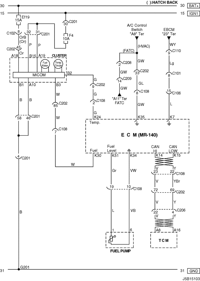
| C208 (15 Pin, White) | I.P – FATC | Behind Glove Box |
| C209 (20 Pin, Black) | FATC – FATC.Aux | Between Heater Core and Evaporator Core |
| G201 | I.P | Left I.P Fuse Block |
|
CONNECTOR NO (PIN NO, COLOR) |
CONNECTING WIRING HARNESS | CONNECTOR POSITION |
| C105 (4 Pin, White) | Body – Engine Fuse Block | Engine Fuse Block |
| C108 (24 Pin, Black) | Body – Engine | Left Engine Fuse Block |
| C110 (12 Pin, White) | ABS – Body | Below Engine Fuse Block |
| C201 (76 Pin, Black) | I.P – I.P Fuse Block | I.P Fuse Block |
| C202 (89 Pin, White) | I.P – Body | Left CO-Driver Leg Room |
| C206 (22 Pin, White) | I.P – TCM | Upper Driver Leg Room |
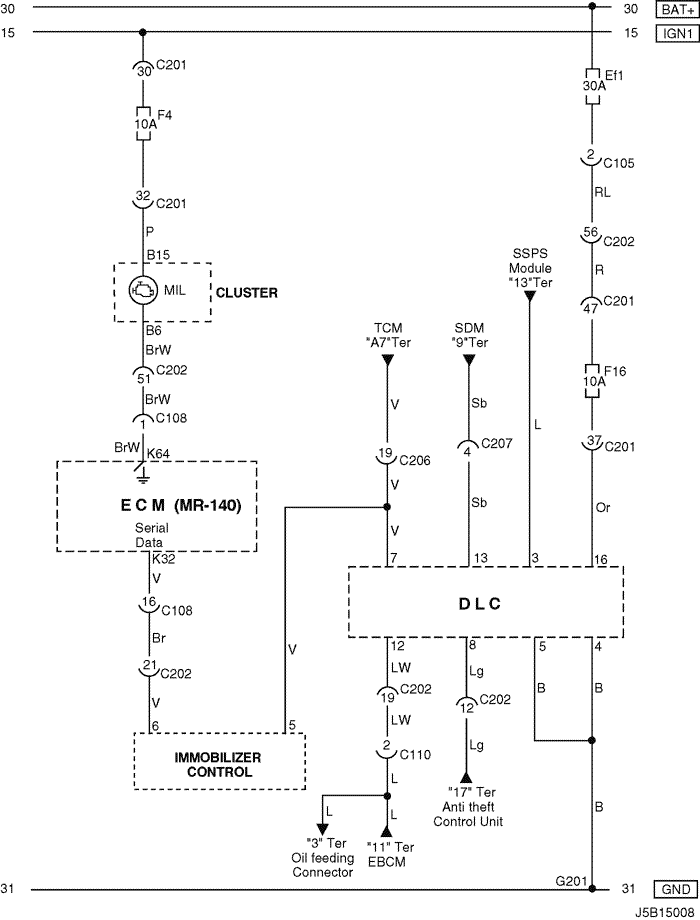
| C207 (6 Pin, White) | Air Bag – I.P | Upper Left Driver Leg Room |
| G201 | I.P | Left I.P Fuse Block |
|
CONNECTOR NO (PIN NO, COLOR) |
CONNECTING WIRING HARNESS | CONNECTOR POSITION |
| C105 (4 Pin, White) | Body – Engine Fuse Block | Engine Fuse Block |
| C108 (24 Pin, Black) | Body – Engine | Left Engine Fuse Block |
| C110 (12 Pin, White) | ABS – Body | Below Engine Fuse Block |
| C201 (76 Pin, Black) | I.P – I.P Fuse Block | I.P Fuse Block |
| C202 (89 Pin, White) | I.P – Body | Left CO-Driver Leg Room |
| C206 (22 Pin, White) | I.P – TCM | Upper Driver Leg Room |
| C207 (6 Pin, White) | Air Bag – I.P | Upper Left Driver Leg Room |
| G201 | I.P | Left I.P Fuse Block |
sm
|
|
|
| © Copyright Chevrolet Europe. All rights reserved |


