21. ELECTRIC OSRV (OUTSIDE REAR VIEW) MIRROR CIRCUIT
a. CONNECTOR INFORMATION
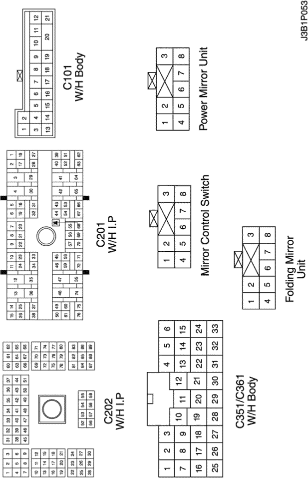
connector no
(pin no, color) | connecting wiring harness | connector position |
| C101 (21 Pin, White) | Body – Engine Fuse Block | Engine Fuse Block |
| C201 (76 Pin, Black) | I.P – I.P Fuse Block | I.P Fuse Block |
| C202 (89 Pin, White) | I.P – Body | Left CO-Driver Leg Room |
| C351 (33 Pin, Gray) | Body – Front Light Door | Under CO-Driver A Pillar |
| C361 (33 Pin, Gray) | Body – Front Right Door | Under Driver A Pillar |
| S302 (Brown) | Body | Left CO-Driver Leg Room |
| G204 | Body | Below Left CO-Driver Leg Room |
| G301 | Body | Below Driver Cross Member Floor Panel |
b. CONNECTOR IDENTIFICATION SYMBOL & PIN NUMBER POSITION
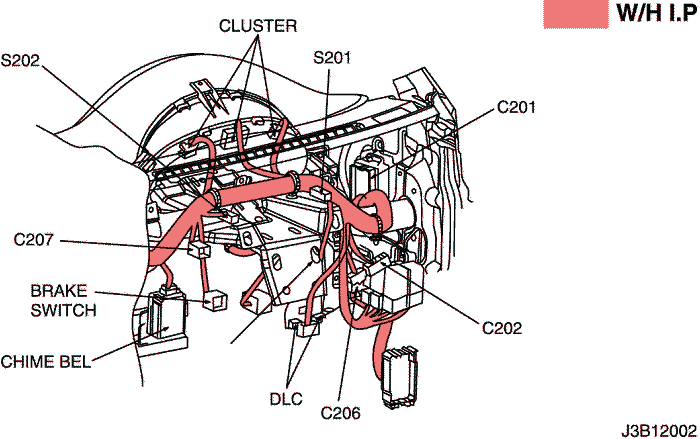
c. POSITION OF CONNECTORS AND GROUNDS
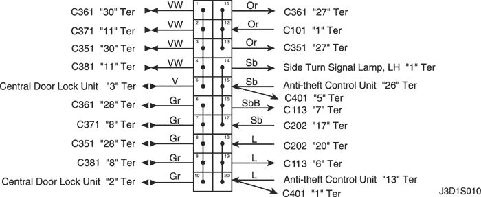
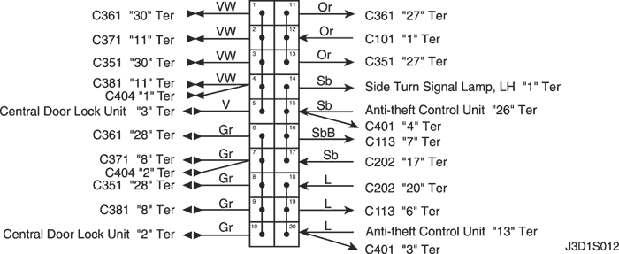
d. SPLICE PACK
s302 (notch back)
s302 (hatch back)
s302 (station wagon)
sm