|
Nubira-Lacetti
|
||||||||
|
|
|||||||
|
CONNECTOR NO (PIN NO, COLOR) |
CONNECTING WIRING HARNESS | CONNECTOR POSITION |
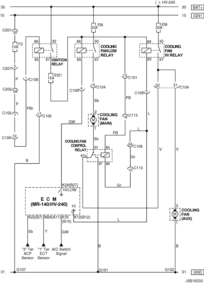
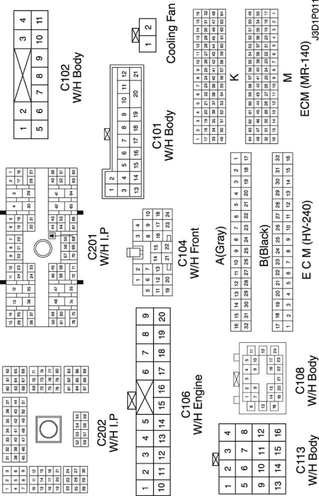
| C101 (21 Pin, White) | Body – Engine Fuse Block | Engine Fuse Block |
| C102 (11 Pin, White) | Body – Engine Fuse Block | Engine Fuse Block |
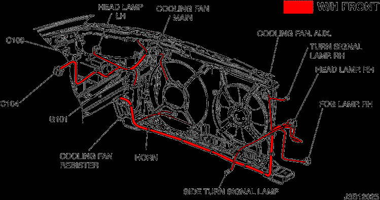
| C104 (24 Pin, White) | Front – Engine Fuse Block | Engine Fuse Block |
| C106 (20 Pin, White) | Engine – Engine Fuse Block | Engine Fuse Block |
| C108 (24 Pin, Black) | Body – Engine | Left Engine Fuse Block |
| C113 (16 Pin, Black) | Body – Front | Behind ECM Bracket |
| C201 (76 Pin, Black) | I.P – I.P Fuse Block | I.P Fuse Block |
| C202 (89 Pin, White) | I.P – Body | Left CO-Driver Leg Room |
| G101 | Front | Behind Left Head Lamp |
| G102 | Front | Behind Right Head Lamp |
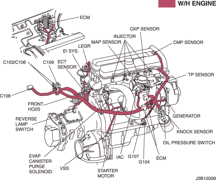
| G107 | Engine (MR-140/HV-240) | Under Start Motor |
|
CONNECTOR NO (PIN NO, COLOR) |
CONNECTING WIRING HARNESS | CONNECTOR POSITION |
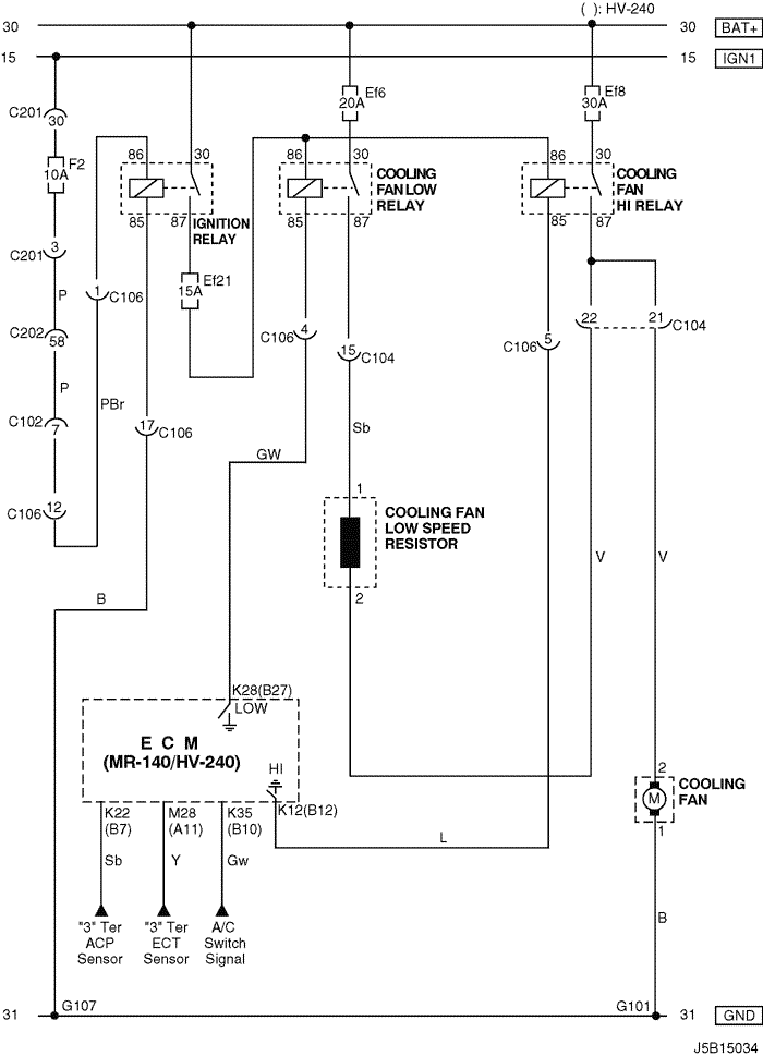
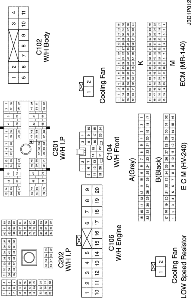
| C102 (11 Pin, White) | Body – Engine Fuse Block | Engine Fuse Block |
| C104 (24 Pin, White) | Front – Engine Fuse Block | Engine Fuse Block |
| C106 (20 Pin, White) | Engine – Engine Fuse Block | Engine Fuse Block |
| C201 (76 Pin, Black) | I.P – I.P Fuse Block | I.P Fuse Block |
| C202 (89 Pin, White) | I.P – Body | Left CO-Driver Leg Room |
| G101 | Front | Behind Left Head Lamp |
| G107 | Engine (MR-140/HV-240) | Under Start Motor |
|
CONNECTOR NO (PIN NO, COLOR) |
CONNECTING WIRING HARNESS | CONNECTOR POSITION |
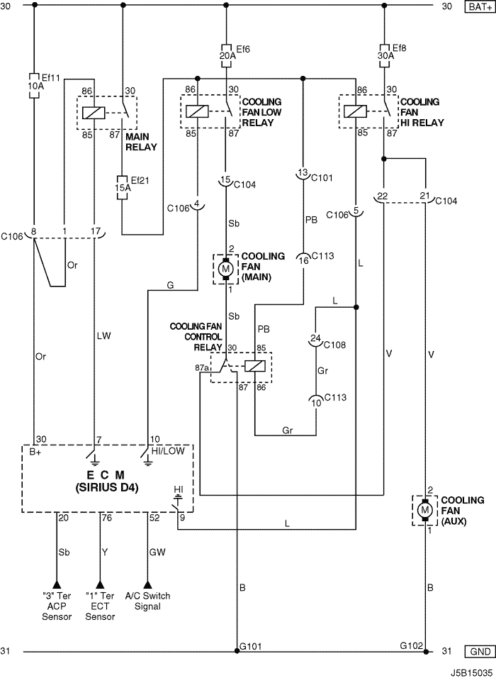
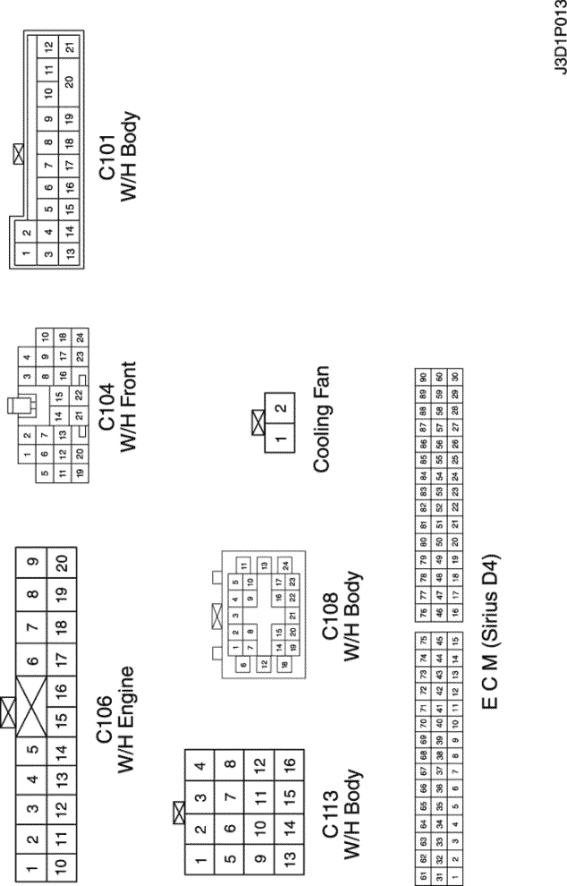
| C101 (21 Pin, White) | Body – Engine Fuse Block | Engine Fuse Block |
| C104 (24 Pin, White) | Front – Engine Fuse Block | Engine Fuse Block |
| C106 (20 Pin, White) | Engine – Engine Fuse Block | Engine Fuse Block |
| C108 (24 Pin, Black) | Body – Engine | Left Engine Fuse Block |
| C113 (16 Pin, Black) | Body – Front | Behind ECM Bracket |
| G101 | Front | Behind Left Head Lamp |
| G102 | Front | Behind Right Head Lamp |

|
CONNECTOR NO (PIN NO, COLOR) |
CONNECTING WIRING HARNESS | CONNECTOR POSITION |
| C104 (24 Pin, White) | Front – Engine Fuse Block | Engine Fuse Block |
| C106 (20 Pin, White) | Engine – Engine Fuse Block | Engine Fuse Block |
| C113 (16 Pin, Black) | Body – Front | Behind ECM Bracket |
| G101 | Front | Behind Left Head Lamp |
sm
|
|
|
| © Copyright Chevrolet Europe. All rights reserved |


